Author Archives: profahmet

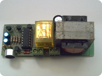
Single Trigger Circuit NE555 Timer

| 2012/11/05

When triggered by a button integrated in the circuit relay 555 timer is energized and immediately set is full when you leave the ignition again. working time is determined by the 220k potentiometer and capacitor C1. Receiving single trigger for the start of timing is sufficient. Trigger Circuit Schematic Diagram

Transistor Adjustable ZENER Diode

| 2012/09/05

Alternative to a zener diode circuit adjustable Zener. According to the current PNP transistor where you will use a more powerful zener diode can be achieved. voltage adjustment every 10k worth of pot 1 and is increasing. Adjustable ZENER Schematic

Digital Controlled Current Limiting Circuit

| 2012/08/04

With this circuit current limitation can set digitally uln2003a. by the combination of resistors R-2 was used. proportional to the binary number value of the current limiting is set. mje3055 2amp load or stronger used transistor.. Current Limiting Schematic

12V AC – 24V DC voltage doubler

| 2012/01/09

12 Volt AC voltage capacitors and 24V DC voltage doubling can be obtained. This dc voltage current, capacitors and transformers of capacity depends on the strength of the bridge diode. How much is all this constant 24v outlet in if you kullanamass efficiently. When the current is not continuous in snatches spend more time charging…

Voltage Protection Circuit

| 2011/07/04

Potentially hazardous voltage spikes on the power supply in a simple circuit can protect your device. Zener 12v low voltage determines the value that can be assigned. 10k potentiometer can set higher values than the 12v. To reset thyristor tic106 the circuit must disconnect the supply voltage. Protection Circuit Schematic Diagram

3-Channel Push Button Selector Circuit

| 2011/02/04

This is a practice used in simple selector circuit. A, B, C are three contenders. The first press of the button Questions and know the warning LED lights Dieren bass even burn later. RESET button LED extinguishes the warning being burnt. Selector Circuit Schematic

Regulated Buck-Boost DC DC Converter Circuit

| 2010/07/04

This circuit is an example of a simple Buck-boost converter circuit. By applying the input voltage from 3v to 15v outlet will receive a fixed value that you set. Determines the minimum output voltage of the zener 10v. You can set the output with 10k pot. You can use it to get a negative voltage…

PIC12F629 Water Level Control Circuit Proton Basic

| 2009/04/20

This circuit controls the water level of water tanks or wells. Three level probes are used in the tank to measure the water level. These are conductive rods with a plastic sheath. Probe A determines the top level of water. The B probe determines the level at which the water will be the lowest. The…

Voice and Touch Switch Circuit

| 2008/03/18

The switch circuit works with touch and sound. It can also be used as a simple alarm circuit. The capacitive microphone can be placed on a window, door or an area inside the house, the relay works with impact or sound. The device connected to the relay becomes active (siren, lamp, motor, etc.) When the…

PWM Motor and Power Control with PIC16F84

| 2008/03/05

PIC16F84 4 MHz crystal is connected 100 Hz PWM output produces a pulse width of 10 separate levels are adjusted these values ​​asm software vary from circuit only engine that not all GUS control applications can be used on a frequency of 50 Hz is set inverters driven circuit two buttons have their power levels…