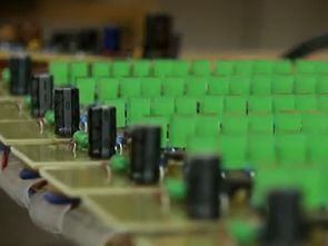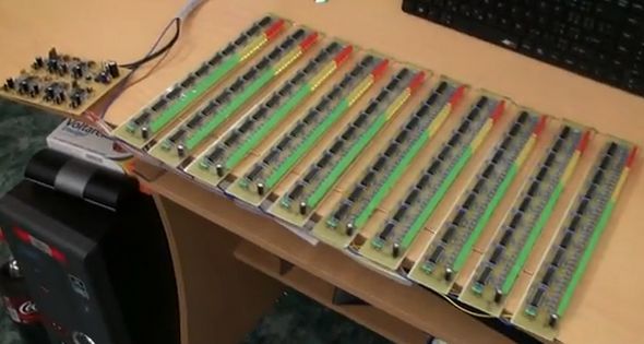
Previously I shared 40 led vu meter circuit using Audio Spectrum Analyzer, Spectrum Analyzer circuit 10 channels (32Hz, 1kHz, 2kHz, 4kHz, 8kHz, 16kHz, 64Hz, 125Hz, 250Hz, 500Hz) on a total of 400 LED’s Spectrum Analyzer circuit 12v DC voltage works with all LEDs illuminated power draws 7.5 amps LM324 op amp used for all integrated control card and vu meter card belonging to the scheme eagle pcb files there .
Main board: Powered by 12V, current is cca 10-15mA To “Stereo input” is connected computer, mp3player, or anything audio source. Outputs from bandpass are signed appropriate frequency.This outputs are connected to “inputs” on VU-meters board. Resistor R5 is main volume to all filters. Output level voltage can be trimmed by trimme on output (R13, R21,…), if that was not enough, just put one resistor between filter output and VU-meter board. Deceleration time of LED column depends on output capacitor (C10,C14,..) you can modified this time, when you change this capacitor(lower value, shorter time to fade down). All resistors are on 0,25W. All capacitors on min. 16V.
VU-meter: Powered by same 12V as main board, current is in peak 750mA. All resistors are on 0,25W. All capacitors on min. 16V. All device peak current: 7,6A.

Source: youtube.com/watch?v=9SK2AxfELfw Audio Spectrum Analyzer circuit PCB schema files:
FILE DOWNLOAD LINK LIST (in TXT format): LINKS-21049.zip
Publication date: 2013/01/21 Tags: analog circuits projects, led projects
Vu Meter Circuit 40 Led
VU meter circuit LM324 op amp based on this circuit a lot of books on the site saw ready vu meter integrated when there is much interest repellent, but this app is also 40 LEDs use and eagle prepared by the PCB drawing the lack of work is changing writers the same circuit 2 have made a total of 80 led vu meter prepare the project in two stereo operation with all LEDs illuminated circuit 12v 2.5 amps draws out … VU meter circuit diagram 12v DC working with the eagle (sch) and PCBs (br) files there ..
Audio Spektrumanalysator Schaltung
Zuvor teilte ich 40 LED-Vu-Meter-Schaltung mit Audio Spectrum Analyzer, Spectrum Analyzer Schaltung 10 Kanäle (32Hz, 1kHz, 2kHz, 4kHz, 8kHz, 16kHz, 64Hz, 125Hz, 250Hz, 500Hz) auf insgesamt 400 LED Spektrumanalysator Schaltung 12v DC Spannung arbeitet mit allen LEDs beleuchtete Macht zieht 7,5 Ampere LM324 Operationsverstärker für alle integrierten Steuerkarte und vu-Meter-Karte, die zum Schema Adler PCB-Dateien gehören dort verwendet.
Main board: Powered von 12V, ist Strom cca 10-15mA Zu “Stereo-Eingang” ist Computer, mp3player oder irgendetwas Audioquelle angeschlossen. Die Ausgänge des Bandpasses sind mit der entsprechenden Frequenz gekennzeichnet. Diese Ausgänge sind mit “Eingängen” auf der VU-Meter-Platine verbunden. Der Widerstand R5 ist die Hauptlautstärke für alle Filter. Die Ausgangspegelspannung kann durch Trimmen am Ausgang getrimmt werden (R13, R21, …). Wenn das nicht genug ist, setzen Sie einfach einen Widerstand zwischen den Filterausgang und die VU-Meter-Platine. Die Verzögerungszeit der LED-Spalte hängt vom Ausgangskondensator (C10, C14, ..) ab. Sie können diese Zeit ändern, wenn Sie diesen Kondensator ändern (niedrigerer Wert, kürzere Zeit bis zum Abblenden). Alle Widerstände sind auf 0,25 W. Alle Kondensatoren auf min. 16V
Hi,
I use the code for the link
thank you very much!!!
Hi, https://320volt.com/wp-content/list/21049.zip pass. 320volt.com