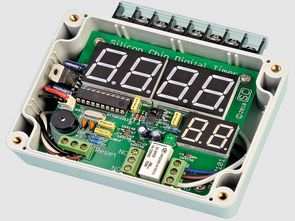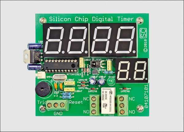
Based on Atmel ATtiny2313 microcontroller circuit with the remote control forward / reverse control can be done over time led display are viewing. ATtiny2313 by the time specified number 9 which is connected to pin PD5 trying to relay is happening.
RC5 protocol used for remote control of the circuit can be used any source control settings sigot c hex codes, pcb, diagrams, dimensions, etc. dry. There are files.
Digital Timer Circuit Remote Control

The circuit is based on the atmel attiny2313 microcontroller and can be controlled forward/backward with a remote control and displays the time on the LED display. The relay connected to the pd5 pin number 9 of the attiny2313 is activated according to the determined time.
Any remote control using the RC5 protocol can be used for remote control, the circuit has source c codes, fuse settings, hex, pcb, schematics, dry measurements, etc. files.
Remote Control Digital Up/Down Timer
This remote control digital timer has a bright 7-segment red LED display with a height of 20 mm and can count up or down from one second to 100 hours in 1-second steps. The timing period can be set and controlled using the remote control or automatically controlled with external trigger/reset inputs. An internal relay and buzzer are activated when the unit times out.
This new digital timer is a very flexible project. We can think of many uses for this, but we’re sure there are many more we haven’t considered.
We’ve made many timers before, but this one has the convenience of a remote control. The timing period can be programmed using the numeric keypad button on the remote, while the remote’s Power/Standby button provides a Reset function.
The simplest way to use it is as a kitchen timer. In this mode, it can count up or down for the timing period, as entered via the remote’s keypad. Pressing the Channel Up button on the remote will cause the unit to count up to the programmed time, while pressing the Channel Down button will count down.
When the time is up, the LED display will flash and a beep will sound for a preset time (the default is one minute) or until the reset button is pressed. You can use the Power/Standby button on the remote or an external reset button to reset the unit.
The internal relay will also switch at the end of the timing interval. This relay can directly control a DC device (30V DC or 24V AC max) or indirectly control a mains powered device via a separate external mains rated relay (see panel). However, please note that this unit is NOT RATED to directly switch mains devices.
By default, the relay is energized when the timer is running. Therefore, the timer can be used to run an oven for a programmed time period, expose a PC board to UV light, or run a fan or light for a fixed period, etc.
The trigger and reset inputs can be used to automatically start and stop the timer when certain events occur, such as when a door is opened, an external button is pressed, or a PIR (passive infrared) sensor is triggered by motion, etc. You can set it to turn on a light or fan when a door is opened, and then turn it off when the door is closed or after the programmed time has elapsed.
It can even be used as the basis of a very simple alarm system. All you need to do is connect a PIR sensor to the trigger input, a key switch to the reset input, and a siren to the relay. Then you set the timer to a short time (say 30 seconds) and the alarm duration to a longer value than the default (say three minutes) and voila! . . . you have a basic motion-triggered alarm with key disable.
By the way, the unit will work with almost any universal remote control that can transmit Philips RC5 codes (almost all do). So if you have a spare universal remote control, it will do the job quite nicely.
Now look at Figure 1 for the full circuit details. The microcontroller is based on IC1 plus three pairs of 7-segment LED readouts. However, instead of using a PIC micro as in many other projects, this time we chose an Atmel ATTiny2313 with 2048 bytes of flash memory.
The micro normally operates at 8MHz, as set by an internal 8MHz oscillator and crystal X1. This clock frequency is reduced to 1MHz (via a clock divider) when the micro is in standby mode.
Note that although the Micro does have an internal 8MHz oscillator, the crystal is required for accurate timekeeping. Typical crystal error is less than 100 ppm, or 0.01%, and although it is normally well below half that, the maximum timing error is one second in three hours.
The unusual part of this circuit is how the six 7-segment LED digits (DISP1-3) are driven. Only 10 of IC1’s 20 pins are used to drive the 48 segments (seven plus six decimal points per digit). We also did not use any discrete transistors or current-limiting resistors in the LED driver circuit. This makes the project smaller, cheaper, and easier to build, but how do we get around this?
First, a “charlieplexing” system (Charl on the Maxim) reduces the number of pins needed to drive the LEDs. ie Allen) is a special form of multiplexing, and to understand how it works, first consider viewing DISP1. This contains two of the digits and has 10 pins – two shared anodes and eight shared cathodes.
Source: http://www.siliconchip.com.au/cms/A_112071/article.html Atmel ATtiny2313 Digital Timer Circuit Alternative link:
Şifre-Pass: 320volt.com
Publication date: 2010/11/29 Tags: avr project, microcontroller projects
High-Power 30A DC Motor Speed Control Circuit PWM LM358 CD4093
DC motor speed control circuits 12 … 32 volts 30 amps of power can operate with speed control PWM technique is done “Reversible” reverse, flat-control feature. Circuit LM358, CD4093, and IRF2804 MOSFETs based on the 5k kotrol speed potentiometer or “hall effect throttle” denier can be done with the joystick.
12-32V 30A motor speed control soft start circuit, relay switching motor direction PWM speed control circuit
30A Motor Speed Control Circuit