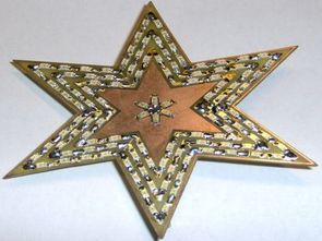
Stars in the shape of hard work to prepare printed circuit board design for SMD LEDs to be mounted like a great deal of attention and effort, but finally emerged quite nice circuit noncontiguous clusters of LEDs flashing creates a beautiful image. 114 pcs SMD LED effects used in the circuit.
ATTINY13 eagle printed circuit control board regulations drawn with different shapes can be achieved by making the source code files have bascom.
The inspiration for creating this design was the Tricolor Star, which was published in A-Radio PE12/01. Back then, I built it right away, and apart from the broken cables, it runs reliably to this day. However, its big disadvantage is that it is controlled by a large and cumbersome plane with 5 IOs and the impossibility of changing the flashing mode.
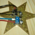
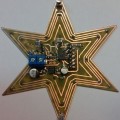
During the long winter evenings I spent time designing and fine-tuning the DPS star, I used SMD LEDs, increased their number and added blue color to the center of the star. I managed to stuff the control part on the other side of the PCB, everything in SMD, and the ATtiny13 microprocessor now takes care of the running of the star.
Function: Schematically, this is a simple circuit. 12V power supply for LED, 5V stabilizer for powering the processor. Then the processor itself with the ISP connector and outputs via transistors to 4 LED colors (of which there are many).
The LEDs are connected in series-parallel so that they use the 12V power supply as much as possible and at the same time “fit” into the structure of the star.
Before the final installation, it is not a bad idea to connect the resistors R11, 12, 13 and 14 for a trial (or even a trimmer) and compare the light of the individual LEDs and, if necessary, adjust their values so that the current through these R does not exceed 150mA (even so, these resistors are well stressed) .
Construction Since the star is composed exclusively of SMD components, you need to prepare a firm hand and a lot of patience for several hours of delicate work.
First you need to install all the LEDs, here it is important to carefully monitor the polarity of the LEDs and gradually lab. measure the LED and the already soldered part of the tip of the star with a source with a primary resistance. The mistake will be made immediately :-). This is how all 114 LEDs are installed (it really takes an hour). Then transitions to the bottom (bottom) layer of the plane are created from pieces of wire or cut off component legs. This would complete the Top (upper) layer.
On the bottom side, the components from the smallest to the largest are classically installed … except for resistors R3 and R4! It will be your turn only after programming the processor!!! I recommend tinning the copper plates under the terminal block, because they must be soldered from both sides – they also form transitions from top to bottom! After the processor is soldered, a bent serial connector for ISP programming is also installed, where the plastic must be reached (moved) close to the bend of the legs and the other part of the legs, which is soldered to the plane, is shortened.
Resistors R11, 12, 13, 14 are doubled (in parallel) due to high temperature stress, but they still heat up decently.
To attach the star to the wire, for example, I put gutted “pins” from the screw terminal block into the lower and upper lugs (they also form transitions at the same time – need to be soldered from both sides).
Because the star handles are conductively connected to the red branch, it is NECESSARY to ISOLATE THEM, e.g. attach to a stick, artificial stick, …
Revival:
With proper soldering and avoiding inattention, the individual LED colors should light up by applying +5V through the resistance to the base of the transistors, ideally before installing the processor. If there is also 5V on the stabilizer, then it is time to solder the processor and the ISP connector. After programming the processor, R3 and R4 can be added (or put on the appropriate pins of the ISP connector by trial and error), then just connect the stabilized 12V/0.5A and the star should flash. If someone wants, they can freely modify the program according to their own needs.
R3 and R4 are not installed because the pins they are connected to are also used for ISP programming, which of course would not work.
LEDs ATTINY13 image effects work;
Şifre-Pass: 320volt.com
Publication date: 2011/01/28 Tags: avr project, led projects, microcontroller projects


3.3V DC to DC Converter Circuit LM2575 Power Supply
Switched dc 3.3v switched 12 volt dc voltage converter circuit allows reducing the 3.3 volt output. LM2575 operating frequency of 52 kHz to 1 amp of 80% power efficiency.
LM2575 step-down (buck) switching regulator
LM2575 series of regulators are monolithic integrated circuits that provide all the active functions for a step-down (buck) switching regulator, capable of driving a 1A load with excellent line and load regulation. These devices are available in fixed output voltages of 3.3V, 5V, 12V, 15V, and an adjustable output version.