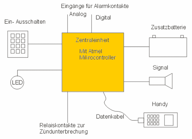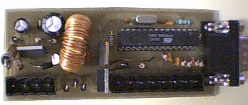
In addition to the “normal” functions of a motorcycle alarm system, it has the following features: Own power supply. Cell phone call signal. Only a few systems that cost several hundred euros have this functionality. Listening to the motorcycle by calling the mobile phone Help with installation problems through our friendly colleagues at Honda Bol d’Or Board 🙂 🙂
The digital alarm input is a normally closed contact. The analog input is disabled when there is a certain resistance to +12V. It reacts to interruptions and short circuits. Several alarm contacts can be connected in series.

A. Mechanical Theft Protection: Included here for completeness purposes only. This means the heavy curb chain on the saddlebag.
B. Alarm signal: Transistor Q1 turns the alarm contact to ground. Any alarm siren offered for alarm systems can be connected. (See iBay under “Alarm Siren”). Even something like this is possible: CLICK
C. Driver alerts: An old Siemens mobile phone can be controlled with modem commands and will dial the first number in the phone book when there is an alarm. So you can easily change the target number. If you turn it on, you can listen to the conversations around the moped. It is also possible to listen while making a call. After the 3rd ring, the mobile phone turns on.
D. Motor stall: The relay for this is not on the circuit board. In the event of an alarm, the relay pulls 1 and can cut one of the blue wires between the CDI and the ignition coil, for example (arrow in the picture). Or both if you use a relay with 2 openers or connect 2 relays.
E. Vehicle tracking: Tracking is possible if the mobile network operator offers it.
F. Theft detection: First of all, the alarm system must be secured against sabotage. For this, we stick a small magnet on the left side cover with 5MinutenEpoxy. A transmitter (reed contact) from a cycling computer can be attached to the opposite steel tube. Normally the contact is closed. If necessary, the right side cover is fixed in the same way.
I. Power source: The easiest way to use an additional battery is to use 8 alkaline mignon batteries in a suitable holder. They almost never self-discharge and therefore last for many years as they are normally inactive. The auxiliary battery is connected to the circuit with 2 diodes. Motorcycle battery via a Schottky diode. This results in a potential difference of 2*0.7V-0.3V = 1.1V. Our 8 mignon cells have exactly 12V. This means that when the voltage of the motorcycle battery drops below 10.9V, the circuit is powered by current from our auxiliary battery. However, this should only be valid for a short time during startup.

Sourcw: stegem.de/Elektronik/Bollealarm/index.htm ATmega8 Motorcycle alarm circuit alternative link:
Şifre-Pass: 320volt.com
Publication date: 2008/09/05 Tags: atmega8 projects, avr project, microcontroller projects
ATmega128 MMC Card Supported 3-Colors LED Sign Message Board
ATmega128 microcontroller based on the ATmega128 a quality marquee project instead of text information stored on the MMC card codes shared resources