Serve to control the 128×64 graphic LCD with a preview of the contents of the array and menu graphics. The heart of the controller is Atmega 128 CPU for communication with the PC corresponds to the FTDI FT232BM. As today is the prototype implemented a very simple menu on the display + 3-button keypad. A fully functioning transmission to PC and oscilloscope generated in real time. On the photos you can see the prototype and actually his half (motherboard) and connected to the test display, in the future all will be on the plate interface.
The driver array is a device intermediary in the transmission of data from the computer to the array, but also allow her to work autonomously without a PC. It is a project that is constantly evolving. Basic features include:
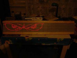
LED Signs LED Matrix Animation Test
– Transmission of PC => array via USB
– Supports SD / MMC card
– Visualization of real-time audio
– Text from the keyboard in real time
– Supports LAN
– Parallel port for different types of applications
– And who knows what else figure it out 😉
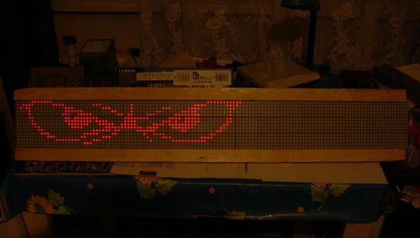
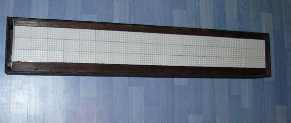
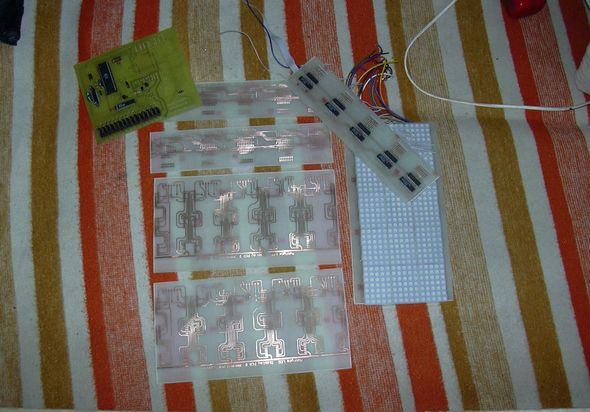
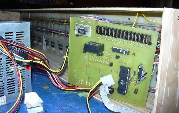
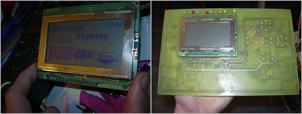
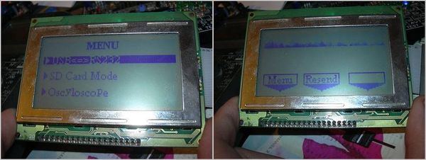
Atmega32 microcontroller circuit boards control is provided via a computer loaded with animation effect can show writings PCB schematics and software files are
Source: matryca.blo.pl Computer Controlled LED Signs PCB source code schematic alternative link:
Şifre-Pass: 320volt.com
Published: 2008/04/19 Tags: avr project, microcontroller projects
TDA1516BQ Amplifier Circuit with PC Card PCB
Almost all modern sound cards are no longer integrated audio amplifier. For all those who have no external active speakers on the PC operating system, is This small stereo amplifier with a sine wave output power of 2 x 3.5 W conceived. Thus, any passive boxes with impedance between 4 ohm and 16 ohm directly connected to the PC. The compact amplifier is in a bracket mounted and is in the PC Built, the power supply is directly on the PC power supply.
TDA1516BQ Amplifier Circuit