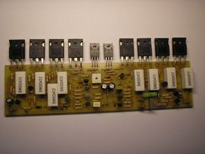
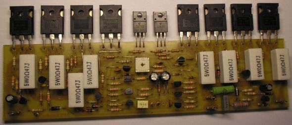
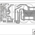
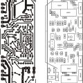
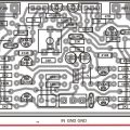
Apex 340W MOSFET amplifier circuit power stage 4 in the IRFP240 (N-Channel) and 4 IRFP9240 (P-Channel) MOSFET used 8 ohm speakers with the RMS 240W into 4 ohms and 340W Power can give printed circuit resettle plan and scheme, further circuit protection floor is in rectifier and filter circuit this section, but only residential floor plan has the same print but in the material values and PCB layout drawings for printing as it seems What can be copied.
Published: 2011/08/20 Tags: audio amplifier circuits, transistor amplifier
ATEMGA168 TLC5940 PWM RGB Led Cylinder
95 pieces made using RGB LEDs Led cylinder project quite professional printed circuit board, software quality circuit that is used quite ATEMGA168 microcontroller with integrated LEDs TLC5940 LED driver plowed. Installation was very difficult olmasy RGB LEDs makes the circuit very nice effect, but I made certain to be very puzzling. Also prepared with eagle pcb source, schema tlc5940.lb source C library and ATmega168, given java code.
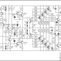
Thanks for publishing the schematic. I do have a question about that as I’m unfamiliar with several of the abbreviations you have on it. On the power side of the schematic, you have “PRO” that is below the +75V input, “LDP” and “LDN” that comes off of Q21 (BC546) and “Clip” that also is at the same location (my assumption is that these are joined with a diode of some type between. What diode is used there?). What are the meanings of these and what do they do?
Hi You’re welcome,
The “Clip” connection will be the LED diode.
Optional additional protection circuit is connected to the “PRO” connection;