Any aquarium hobbyist knows how important it is to know and control the conditions of the aquarium water for the smooth development of life in it. One of the factors that determine these conditions is the acidity or pH value of the water.
Unfortunately, quality pH meters are extremely expensive. With that in mind, I decided to design and build a pH meter that would combine precision and reliability at a not very high cost.
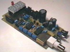
The result is the assembly described below, whose most notable features are:
Accuracy: Better than 1%.
Measuring range: pH 0 to pH 9.99.
Probe Type: Standard
Adjustable pH too high and too low alarms.
As the author, I wish this design to be beneficial to the aquarium community, and I would like to receive your criticisms (positive or negative) and suggestions. Likewise, I will try to clarify any doubts that may arise and keep this project updated. For all this, my e-mail address is at your disposal.
Since we will be using a standard pH probe, we will start by explaining how it works on an electrical level. Theoretically, a pH probe provides its output with a voltage inversely proportional to the pH of the liquid, taking the neutral pH as zero. That is, the output voltage for pH 7 is 0V; When pH is greater than 7, the output voltage is negative, and when pH is less than 7, the changes are about 60mV per pH grade.
For example, the output voltage will be around 120mV for pH 5 and -90mV for pH 8.5. I said this is theory because the truth is that depending on several factors (quality and aging of the probe, temperature etc), it may not give exactly 0V for pH 7 or voltage spikes are not normal. 60mV per pH grade. For all this, the circuit will need to be calibrated periodically so that its measurement is reliable.
We will now schematically summarize what our circuit will do with this data. The voltage reaching the circuit: First, the input voltage is amplified to bring it to an appropriate level. This amplifier multiplies the input voltage by about 1.7, so at its output we get:
Next, we have a circuit that subtracts this voltage from another reference voltage of 0.7 V, which we will have at its output: and after the input amplifier and the 0.7V reference are adjusted, we will have: i.e. 100mV per pH degree. It only remains to add a voltmeter on the tenth scale of a volt to get a direct pH reading.

In addition, there are a number of low-pass filters with a cutoff frequency of about 10 Hz to eliminate noise and interference, and some comparators by two adjustable voltage references to generate alarms.
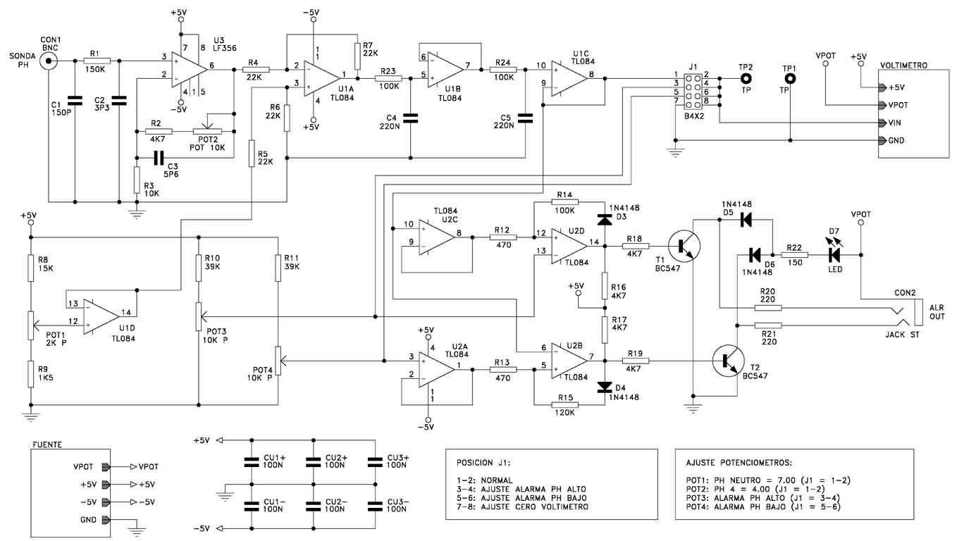
The output of the probe is connected to amplifier U3 through a 10Hz low-pass filter consisting of R1, C1 and the probe’s own internal resistance. These components and the traces connecting them to U3 and the connector of probe CON1 form a true antenna, so the length of the traces should be minimized.
The operational amplifiers U3, together with R2, R3 and POT2, form a non-inverting amplifier whose gain can be adjusted from about 1.5 to 2.5. This operational amplifier model (LF356) and this configuration was chosen because of its very high input impedance, greater than one Tera-ohm (1012 ohm).
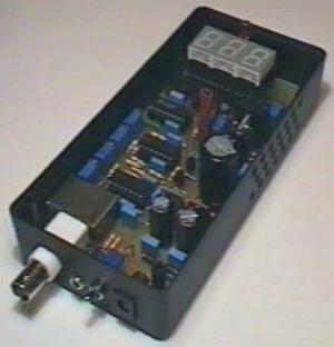
Please note that the output impedance of the probes can reach several Giga-ohms. For probes with higher output impedance, the gain may need to be increased further. In this case, the POT2 can be replaced with an adjustable multi-turn of 20K or 50K. Capacitors C2 and C3 are a protection against noise from self-oscillation recommended by the manufacturer of the LF356 (National Semiconductor). In my design, this entire block is protected against interference by a metal box.
The voltage divider created by R8, R9 and POT1 creates an adjustable voltage reference between 400mV and 950mV. Since the current flowing through them is minimal, the temperature of the resistors will depend almost entirely on the ambient temperature, and since they have equal temperature coefficients, the relationship between them and thus the voltage reference will remain constant.
This reference voltage is taken through the voltage follower U1D to the positive input of the subtractor, which consists of U1A, R4, R5, R6 and R7. The purpose of the voltage follower U1D is to make the voltage reference independent from the rest of the circuit. The output of the U3 input amplifier is applied to the negative input of the extractor.
To maintain the sensitivity of this subtractor, it is appropriate for R4 to R7 to be 1% precision resistors. The circuit is set to 22K, but they can be anywhere from 10K to 50K as long as they are all the same. The linearity of the circuit largely depends on the equality of these resistors, so it would not hurt to measure them with a digital multimeter, for example, to buy 10 resistors and choose four as similar as possible.
The next step, consisting of U1B, U1C, R23, R24, C4 and C5, is a two-stage low-pass filter with a cutoff frequency of about 10 Hz to remove the noise accumulated in the previous steps. Under normal operating conditions, the output of U1C is connected to the voltmeter via jumper J1. At this point, we have a voltage between 0V and 999mV, which corresponds to the measuring range of the voltmeter and pH levels between 0 and 9.99. We’ll dig deeper into the voltmeter later, but assume it will give a reading between 0.00 and 9.99, corresponding to voltages between 0V and 999mV. This output is also used for pH too high and pH too low alarm circuits.
The trigger level of the pH too high alarm is set by the voltage reference consisting of R10 and POT3, while that of the pH too low alarm is set by the voltage reference consisting of R11 and POT4. Both are adjustable in the range of approximately 0V to 999mV. The U2D is configured as a voltage comparator; Its positive input is connected to the output of U1C whose voltage corresponds to the measured pH through the U2C voltage follower, while its negative output is connected to the voltage reference corresponding to the pH too high alarm.
When the measured pH is higher than that set by POT3, the output of the U2D switches to its positive state, which is equivalent to about 4V; otherwise it goes into negative state, i.e. about -4V. D3, R12, and R14 introduce a hysteresis (the difference between the low-to-high-state switching voltage and the high-to-low-state switching voltage) of approximately 0.12 degrees pH. If we call the voltage at the positive input of U2D VIN, the voltage at the output of U2D VOUT and the voltage drop across the diode D3 VD3, the value of the hysteresis voltage can be calculated as: and since the voltage at the two inputs of U2D at the moment of commutation is practically the same, we get:
VALR is the voltage set for the pH too high alarm. For example, if we set the alarm to trigger at pH 8, the VALR would be 0.8V and the hysteresis would be: this is equivalent to 0.12 degrees pH. That is, the alarm will sound when the pH rises above 8.00, but not until it falls below 7.88. The hysteresis level can be changed by changing the value of R12 or R14 according to the previous formulas and even lowered to 0 by eliminating R14 and D3, but if the alarm output is intended to be used to activate a pH corrector, then that device should not receive very short pulses and instead always leave some hysteresis to run for longer periods of time until the level is corrected k will be required.
When the output of the U2D is positive, i.e. the pH is higher than the pH set for the pH too high alarm, T1 turns on and current flows through D5, R22 and D7 so the LED lights up. Similarly, if an optocoupler LED is connected to the alarm output, it will transmit over R20 and activate the external device. With these values, the cable going to the external device in question can measure up to 5 meters without the need for shielding. For longer lengths, R20 can be used instead of a 150 ohm resistor. When an external device is connected, it will always be done through an optocoupler, taking into account that the common point of the connector corresponds to the anode of the internal LED of that optocoupler.

PH Meter Circuit schematic pcb files alternative link:
Şifre-Pass: 320volt.com
Published: 2008/12/01 Tags: analog circuits projects
Eagle Library Archive V4.60 and Above
Popular PCB diagram drawing program for Eagle lb and all attempts to scan library files although I did not warm up to the kind of people who use this program could be useful for Eagle big Library Archive