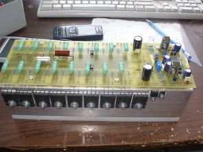
The lowest speaker ohm that can be used at the output of an amplifier circuit based on very powerful bjt transistors (2SA1943 pnp 2SC5200 npn) is 450 watts with 2ohm and 260 watts with 8ohm. The operating voltage is symmetrical +-80 volts dc. The input sensitivity is 1.1 volts. The bandwidth is 10-180,000Hz -3dB.
CAUTION 700 Watt Amplifier circuit works with high voltage be careful pay attention to capacitor connections if you connect the + – poles of the capacitors in reverse there may be big explosions at high voltage before operating the circuit Fused Power Line, use protective glasses
Leach 700W amplifier
It seems easy to set the amplifier to a power of 700W, but we should not forget that when the driver transistors are changed the entire circuit must be frequency compensated again. It is also necessary to adjust the current fuse that serves to protect the end transistors. Its slope should keep the transistors in the permissible part of the SOAr characteristic. First of all, it was necessary to calculate all the necessary resistances and then verify the accuracy of the measurements, this was achieved with a satisfactory result.
Circuit changes required for the amplifier to be able to deliver the required power stably
– First of all, it is necessary to replace the series connected 2k2 resistors with Zener diodes for higher power resistors. 1/2W resistors will be enough, the loss in the +-80V power supply is 1W.
– also, the 1k2 resistor in the feedback loop was replaced with a 620 ohm resistor. As a result, the original gain was doubled, that is, now the total gain of the amplifier is 40, and 1V eff is enough for maximum excitation.
– the transistors in the pre-exciter were replaced with more powerful MJE15032/33, since the permissible collector current of the KF467/470 is 20mA
– the drivers in the final stages are replaced with the same transistors as in the final stage.
– the number of end transistors was increased to 8 pairs
– this required the necessary compensation by adding a 10pF capacitor to the 47pF + 22k element in the driver stage. This caused a slight “slowing down” of the amplifier, but this did not affect the obtained parameters. This capacitance is fine-tuned for this type of 2SA1943/2SC5200 terminal transistors. By the fact that it is the minimum value at which the amplifier works stably without overshoots on the rising and falling edges of the rectangular waveform.
– the last setting is the adjustment of the current protection of the terminal transistors. From the SOAr characteristic of the transistor it follows that the maximum permissible collector current is 1.5 A at this voltage, i.e. with ideal cooling, so in reality it is less. Therefore, the current protection is set to 12A by a branch. In this way, the protection duplicates the SOAr characteristic of the transistor. The short-circuit current is about 6A, which is about 075A per transistor. This is well below the limit in the SOAr characteristic.
The mechanical structure is relatively simple, the transistors are placed on two cooling profiles with a height of 66 mm, a width of 44 mm and a total length of 260 mm. They are turned towards each other, forming a cooling tunnel. The heatsinks are placed on a nylon pad that allows for padless mounting of the transistors and therefore better heat transfer. The amplifier DPS is on top of the tunnel and the transistors are soldered from the bottom of the DPS.
Technical parameters:
Output power: 680W/2R, 450W/4R, 260W/8R
Minimum load: 2R
Bandwidth: 10 – 180,000Hz/-3dB
Maximum permissible supply voltage: +/-80V maximum
Delayed connection: approx. 1.5 seconds
Input sensitivity for maximum excitation: 1.1V
Overshoot speed: 35V/us
Source: jendaelektro.ic.cz
Şifre-Pass: 320volt.com
Published: 2011/02/09 Tags: audio amplifier circuits, transistor amplifier
Tone Controlled Preamplifier Circuit TL072 Opamp
Preamplifier circuit TL072 op amp based on the previously shared “NE5532 Preamplifier tone control” circuit is controlled according to the deeper and a little more powerful stereo two-channel preamplifier and solid bass, treble, balance, volume control. TL072 op amp tone control preamplifier circuit power supply +-12v (7812 7912 negative positive regulator, the regulator) low flow for taking small 12v control by connecting to the circuit in series.