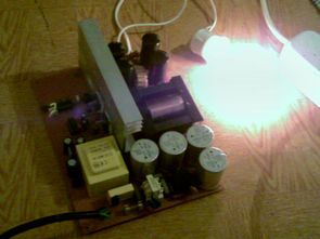
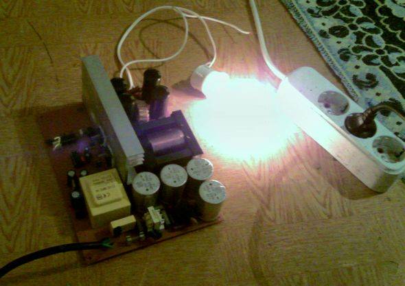
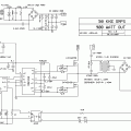
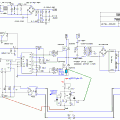
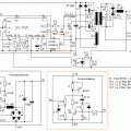
SMPS circuit have 3 version of the 700w (+-50v 50khz), 800w (+-42v 60khz) and 900w (+-70v 50khz) circuit diagrams for the same smps pwm control output is used to drive the integrated MOSFET sg3525 ir2110, but according to some of the values are different, the forces of the output of the SMPS circuit voltajlarına has been prepared with proteus aras 800w pcb çizimide. High power smps circuits that can be used to run symmetric lecture.
Author: @Veysel ARSLAN was a clean, strong thanks to people who contributed to preparing the design.
Short circuit, over-current protection
Circuit only missing overcurrent protection does not have, though the + and – output fuse adding solved this problem but electronically additional protection would not be bad sg3524 and sg3525 SMPS PWM control integrated short-circuit, over-current protection for the 10 numbered “shutdown” pin is used on this pin 5v Near No voltage is cutting the integrated version of the modification for this job, you can use the following (untested) shunt resistance should be done according to the current account to be drawn 0.6 / current

SG3525 Ir2110 SMPS for 2 different pcb diagram:
FILE DOWNLOAD LINK LIST (in TXT format): LINKS-19489.zip
Publication date: 2012/08/11 Tags: ir2110 circuit, power electronic projects, sg3525 circuit, smps circuits, smps projects, smps schematic
Antenna Analyzer Circuit 31mhz 1.3MHz PIC16F873
1.3 MHz 31MHz Antenna Analyzer circuit based on Pic16f873a microcontroller is able to measure between the frequencies of 1.3 MHz 31MHz 2 x 16 lcd on the frequency, omaj, swr, etc displays the information. Antenna Specifications of C source code and pcb, schema, etc. have the drawings.
Hi, can this be used for smps inverter oscillator to regulate the voltage to 220v going to the H bridge or do you have some other diagram?
How can it be if I want get 18v+/-? I’d like to make a 5.1 channel mini amplifier gainclone TDA2050