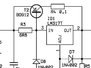
A simple battery charger using the LM317T three-terminal voltage regulator. The maximum output current of the LM317T integrated circuit, which is 1.2 A, is increased by the power transistor (BD912). The maximum output current of the charger is limited to approximately 5.3 A by the R4 resistor. Since there was no 0.55-OHM ready-made stone resistor, 0.33 and 0.22-OHM 10W stone resistors were used in series.
The transformer output voltage should be at least 6 Amps if the 16VAC power is connected to the charger. When a discharged battery is connected to the charger, a large starting current flows, which gradually decreases during charging. The LED goes out if the charging current is less than 1.2 A. A diode and fuse are connected in parallel to the output to prevent the battery from being reversely connected.
50AH Battery Charger Circuit Diagram

Şifre-Pass: 320volt.com
source: paja-trb.cz/konstrukce/nabijecka_autobaterek.html
Publication date: 2024/12/17 Tags: battery charger circuit, power electronic projects