The charger ensures that the battery is charged with a constant current and then recharged after the charging current is reduced. The circuit consists of a full-wave rectifier, a current balancer and a charging current sensor. The current stabilizer works on the principle of limiting the current of the voltage stabilizer.
The charging current decreases as the battery is charged. After reaching the limit value, the battery supply voltage will decrease, i.e. the battery will enter the charging phase. The circuit is designed to charge 12V batteries, but can also be used to charge 6V batteries if the values of the components are changed. Initial charging current 4.5A Final charging current 3A Boost voltage – 13.8V
2X15V AC voltage 6A1 D1, D2 is rectified and filtered by C1 1000uf capacitor. D2 LED indicates that the power is on. Approximately 20V DC direct current is supplied to the L200C regulator. L200C can deliver up to 2A current. It is equipped with a number of protections.
It has an internal reference voltage source of approximately 2.8 V. The output voltage is set by an external voltage divider and its value is calculated with the following formula:

Current limiter: Output current is limited when the voltage between pins 5 and 2 exceeds 0.45 V. The Rs resistor connected in series with the output creates a voltage drop that is used to limit the current when the load current flows. The maximum output current is found by the formula:

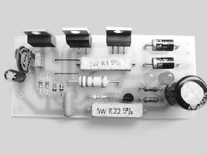
4.5A Charger Circuit Diagram L200C

The BD286 transistor is connected in parallel with the L200C voltage regulator. This transistor is controlled by the voltage drop across the R3 resistor. The transistor’s job is to conduct most of the current to the load and take the load off the regulator. If the regulator current is greater than 0.3A, the transistor will start conducting. At full load (current limiting), about 1.5A of current will flow through the regulator and 3A through the transistor. Due to the heat generated, the BD286 transistor and the L200C regulator IC require the use of a heat sink.
The L200C voltage regulator’s 3rd pin is connected to chassis via diodes D6 and D7. Their job is to protect against the effects of reverse battery connection. They also reveal the dependence of the output voltage on temperature, similar to the characteristics of lead-acid batteries.
The R8 resistor is included in the current limiting circuit. The current value (0.1W) limits the output current to 4.5A. This is an acceptable value for most batteries currently in use. Diode D8 also acts as a balancer connected to the battery without Power On.
The resistors R6, R7 and P1 determine the value of the boost output voltage. The exact value (13.6V….13.8V) is set by P1. During battery charging, the maximum output voltage is increased by connecting the resistor R4 via the T1 BC548B transistor. The battery is charged by the lighting of the LED diode D4, which is also driven by the T1 BC548B transistor.
The T1 BC548B transistor acts as a charge current sensor together with the R5 resistor. When the voltage drop across the resistor exceeds 0.6 Volts, the transistor is turned on. This drop is transmitted to the base of the transistor via the R9 resistor and its current is limited. At the current resistance value, the transistor is turned on and charging is performed if the charging current is greater than 3A.
Charger setup: Set P1 to the middle position. Turn on the power and check the voltage on capacitor C1. It should be around 20V. Connect a multimeter to the output and set the voltage to 13.8V with P1. Short-circuit the collector and emitter of T1. LED D4 should light up. The output voltage should rise to 16÷16.5V.
2X15V Transformer power should be at least 60VA. It is recommended to connect a 500mA fuse to the 220V input. The thickness of the output cables should be at least 1.2mm and their length should not exceed 2m.

Charger Circuit Bill of Materials
US1 L200C
T1 BC548B
T2 BD286 or 2N6107
D1, D2 1N5402
D3 LED (green)
D4 LED (red)
D5, D6, D7 1N4148
D6 6A1
R8 0.1-OHM 1W
R5 0.22-OHM 2W
R3 2.2-OHM 2W
R9 1k/1/4W
R1, R2 1.8k 1/4W
R6, R7 4.7k 1/4W
R4 47k 1/4W
P1 10k TVP 1232
C2, C3 220nF 63V
C4 10uF 25V
C1 1000uF 25V
Şifre-Pass: 320volt.com
Publication date: 2025/03/03 Tags: battery charger circuit, power electronic projects