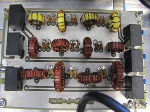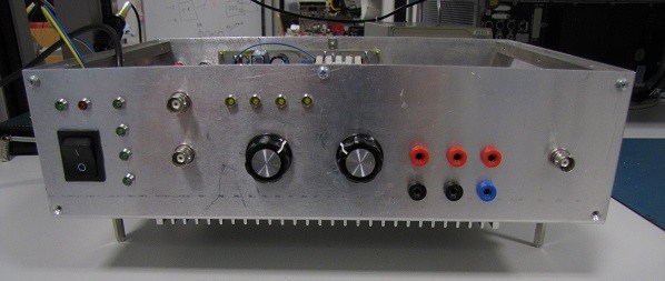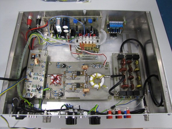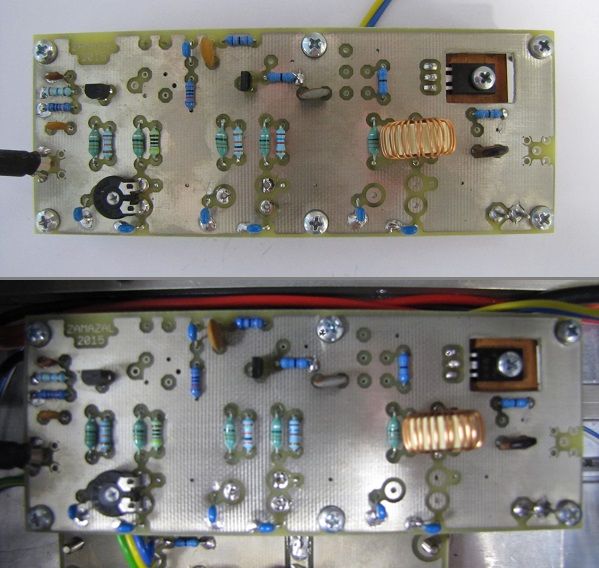
High-frequency RF Power Amplifier is a device that is able to change (amplify) the amplitude of the input signal using power supplied from the power supply. This energy is transformed into the amplified output signal and partly on the heat (the amount of the dissipated power radiated as heat is dependent on the efficiency of the amplifier). It can be seen as the active dvojbran. [1] Amplifier is one of the most widely used device in high-frequency RF Amplifier circuits. From the point of view of the width of the transmitted bandwidth can amplifiers divided into broadband and narrowband. The exact definition, when there is a narrowband amplifier and when the broadband amplifier is not uniquely determined. Generally a narrowband amplifier is considered to be one which satisfies the condition
Power Amplifier RF Circuit


RF Amplifier Base modulator
This type of modulator is referred to as a modulator with low levels. In principle, the modulation signal applied to the base-circuit transposed to the input high-frequency voltage. This type of modulator affects the operating point of the amplifier, and therefore it is with this fact should be considered when its proposal. The efficiency of the modulator is calculated as
RF Amplifier Preamplifier stage
This stage has the task to amplify the input signal for the further processing of the main power stage. My work in the classroom And because of the minimum distortion. Due to maximum simplicity of construction it was decided to takeover catalog wiring of three-stage amplifiers [14]. This wiring had to be modified. For us wrong the available transistors have been replaced by equivalent (BC547, ZTX653 and BD135) and above all it was necessary to modify the working class of second and third tier, which in the datasheet of the involvement of work in the a class. All the wiring has been modified and verified in the environment of OrCad Capture. The power amplifier is 15V.

![]() rf amp circuit pcb schematic all files alternative links:
rf amp circuit pcb schematic all files alternative links:
FILE DOWNLOAD LINK LIST (in TXT format): LINKS-25639.zip
Publication date: 2016/06/10 Tags: analog circuits projects
2X100W Class D Amplifier Circuit HIP4081A
HIP4081A two-channel output stage amplifier working in class D power 2×100 W to the load 8 Ω. For its construction are used mostly SMD components to the parasitic characteristics of the conductive connections shown what at least. The end-amplifier working in class D was designed in the “non-integrated” version in engagement with each of the operational amplifiers, the comparator and the driver Mosfets. His involvement includes a self-oscillating sigma-delta modulator of second order.
30W RF Leistungsverstärkerschaltung Projekt
Hochfrequenz-RF-Leistungsverstärker ist ein Gerät, das in der Lage ist, zu ändern (verstärkt) die amplitude des Eingangssignals mit Stromversorgung aus dem Netzteil. Diese Energie verwandelt sich in das verstärkte Ausgangssignal und teilweise auf die Hitze (der Betrag, der die dissipierte Energie abgestrahlt als Wärme ist abhängig von der Effizienz des Verstärkers). Es kann gesehen werden als aktive dvojbran. [1] Verstärker ist einer der am meisten benutzten Geräte in der Hochfrequenz-HF-Verstärker-schaltungen. Aus der Sicht der Breite der übertragenen Bandbreite kann Verstärkern unterteilt in Breitband-und Schmalband. Die genaue definition, wenn es einen Schmalband-Verstärker und wenn der Breitband-Verstärker ist nicht eindeutig bestimmt. In der Regel, einen Schmalband-Verstärker ist als eine, die die Bedingung erfüllt