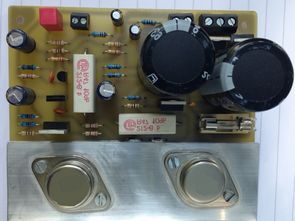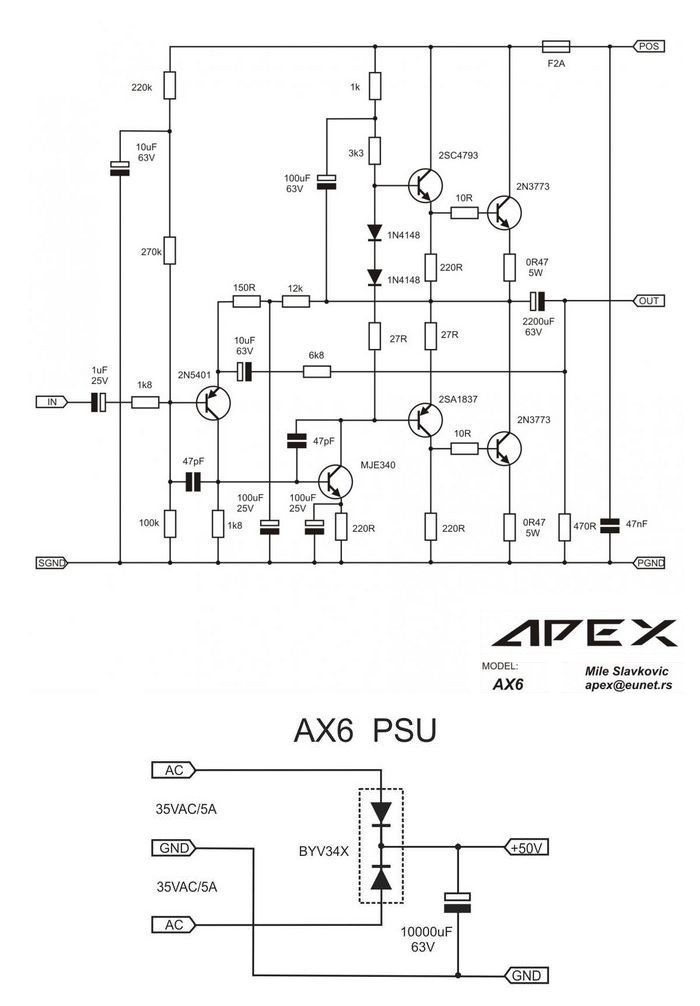
For a long time I was going to share with you the materials on assembling a transistor amplifier with unipolar power, assembled in retro-topology, which is still of interest to some radio amateurs. At the forum Diyaudio this ULF can be found under the name APEXAX6. This circuit does not need DC Protect, because the output of the amplifier is connected to the acoustics via an electrolytic capacitor. The recommended voltage of the secondary winding of the 35V AC transformer, at which the output of the power supply unit will be about 50V DC, the maximum permissible 60V DC. At a supply voltage of 50V DC, the amplifier delivers 35W of power to the load.
Output transistors 2N3773 can be replaced by 2N3055 with power supply up to 60V. In this version of the watering can, as I understand it, compared to the original circuit, instead of the 12k resistor, a multi-turn TrimPot 22k is installed, and instead of the 27R, which is in series with the diodes 1N4148, TrimPot 50R is installed to correct the quiescent current of the output stage transistors.
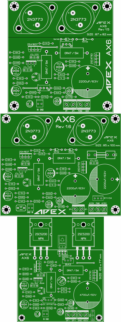
The diameter of the output capacitor on the PCB is 25 mm, you can put 2200mF / 63V, 4700mF / 63V or 6800mF / 50V.
150W Amplifier Circuit Schematic

Bias 20-50mA can be installed with 50R Pot, if the desired BIAS is not installed or you want to increase the quiescent current – increase the nominal value of the trimmer up to 100R … 220R, but you need to use sufficiently large radiators.
The power capacitor can be from 2200mF-63V. As a rectifier, a double ultrafast diode BYV34 is used in the TO-220 package, it is possible to put BYV32 or BYV36. On this board, the input electrolyte 1mF-63V is replaced by 1mF film nonpolar, and a power fuse is added. There are no trim multiturn resistors on the board, because the board author did not want to use them for this circuit. The diodes 1N4148 in versions 1.5 and 1.6 are in thermal contact with the output transistor heatsink, that is, they are pressed against it using thermal paste. The recommended transformer is 2x36V AC 75W for MONO or 150W for STEREO.
In this 2SC5200 version of the board instead of diodes 1N4148 added transistor MJE340, which is installed on the radiator along with the output transistors. For all transistors installed on the radiator, do not forget the insulating pads and thermal grease.
150W Amplifier PCB Desings

Transistors:
? 2N5401 – 1 pc.
? MJE340 – 1 pc. (2 pcs.)
? 2SC4793 – 1 pc.
? 2SA1837 – 1 pc.
? 2N3773 (2SC5200) – 2 pcs.
Diodes:
? 2BYV32 (BYV34 or BYV36) – 1 pcs.
? 1N4148 – 2 pcs.
Resistors:
? 1k8 – 2 pcs.
? 220k – 1 pc.
? 270k – 1 pc.
? 100k – 1 pc.
? 150R- 1 piece.
? 12k – 1 pc.
? 6k8 – 1 pc.
? 220R – 3 pcs.
? 1k – 1 pc.
? 3k3 – 1 pc.
? 27R – 2 pcs.
? 10R – 2 pcs.
? 470R- 1 pc.
? 0R47 / 5W – 2 pcs.
? TrimPot 50R, TrimPot 200R, TrimPot 22k – depending on the version of the board.
Capacitors:
? 1mF / 25V electrolyte or film – 1 pc.
? 10mF / 63V electrolyte – 2 pcs.
? 47p – 2 pcs.
? 100mF / 25V electrolyte – 2 pcs.
? 100mF / 63V electrolyte – 1 pc.
? 47n – 1 pc.
? 2200mF / 63V electrolyte – 1 pc.
? 2200mF / 63V electrolyte for version with power supply – 1 pc.
In the near future I will try to share with you the circuit and board of the stabilized regulated power supply, which the author recommends using for the APEX AX6 amplifier, the board of which does not have a rectifying superfast diode and a smoothing capacitor for power.
pcb drawing was made with Sprint-Layout free viewer; https://www.electronic-software-shop.com/lng/en/support/free-viewer-software/
FILE DOWNLOAD LINK LIST (in TXT format): LINKS-26010.zip
Publication date: 2018/05/17 Tags: audio amplifier circuits, transistor amplifier
2N3773 2SC5200 Verstärkerschaltung 150W
Lange Zeit wollte ich mit Ihnen die Materialien zum Aufbau eines Transistor-Verstärkers mit unipolarer Leistung teilen, der in Retro-Topologie zusammengebaut wurde und für einige Funkamateure noch interessant ist. Auf dem Forum Diyaudio kann dieses ULF unter dem Namen APEXAX6 gefunden werden. Diese Schaltung benötigt keinen DC Protect, da der Ausgang des Verstärkers über einen Elektrolytkondensator mit der Akustik verbunden ist. Die empfohlene Spannung der Sekundärwicklung des 35 V AC-Transformators, bei der der Ausgang des Netzteils etwa 50 V DC beträgt, die maximal zulässigen 60 V DC. Bei einer Versorgungsspannung von 50 V DC liefert der Verstärker eine Last von 35 W.
Die Ausgangstransistoren 2N3773 können durch 2N3055 mit einer Stromversorgung von bis zu 60 V ersetzt werden. In dieser Version der Gießkanne, wie ich es verstehe, im Vergleich zu der ursprünglichen Schaltung, anstelle der 12k-Widerstand, ein Multi-Turn-TrimPot 22k installiert ist, und anstelle der 27R, die in Serie mit den Dioden 1N4148, TrimPot ist 50R ist installiert, um den Ruhestrom der Endstufentransistoren zu korrigieren.
Der Durchmesser des Ausgangskondensators auf der Leiterplatte beträgt 25 mm, Sie können 2200mF / 63V, 4700mF / 63V oder 6800mF / 50V verwenden.
150W Verstärker Schaltungsschema
Circuit amplificateur 150W
Pendant longtemps, j’allais partager avec vous les matériaux sur l’assemblage d’un amplificateur à transistor à puissance unipolaire, assemblé en rétro-topologie, qui intéresse toujours certains radio-amateurs. Sur le forum Diyaudio, cet ULF se trouve sous le nom APEXAX6. Ce circuit n’a pas besoin de DC Protect, car la sortie de l’amplificateur est connectée à l’acoustique via un condensateur électrolytique. La tension recommandée de l’enroulement secondaire du transformateur 35V AC, à laquelle la sortie de l’unité d’alimentation sera d’environ 50V DC, le maximum admissible 60V DC. À une tension d’alimentation de 50 V CC, l’amplificateur délivre 35 W de puissance à la charge.
Les transistors de sortie 2N3773 peuvent être remplacés par 2N3055 avec une alimentation jusqu’à 60V. Dans cette version de l’arrosoir, si je comprends bien, par rapport au circuit d’origine, au lieu de la résistance 12k, un TrimPot 22k multi-tours est installé, et au lieu du 27R, qui est en série avec les diodes 1N4148, TrimPot 50R est installé pour corriger le courant de repos des transistors de l’étage de sortie.
Essa configuração é classe A ou AB?
Class AB amplifier.