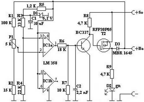
Solar regulator circuit power 15 amp circuit LM358 op amp based on the integrated output RFP30P05 (30 amp 50 volt) MOSFETs kullanılmışpiyasa the transaxle I do not know, but P-Channel appropriate MOSFETs available battery charge voltage 14.4v set to have been 5k trimpot these values are edited.
Solar panels are connected in series in shock diodes (Schottky MBA 1645) is saying you can not find in your area can be found in the PC power supply 5V output

When they check the efficiency of solar charge controllers, they will definitely surprise everyone. Very simple, just connect the solar panels directly to the battery once and measure the charge current with an ammeter. Then disconnect, switch on the controller and measure the charge current again. The device must of course be connected between the batteries and the charge controller.
I did this with our first solar controller that we bought. After a long time making it safe, I developed the simple but very effective controller presented here, which lives a long time and gives nothing away.
It has proven itself in our years of wandering around. I use the same components in all my controllers to keep the need for spare parts as low as possible.
This controller wastes none of the valuable solar energy. This means that as soon as the set end-of-charge voltage, for example 14.4 volts, is reached, the battery is not yet fully charged. If we were to charge it higher, the battery would gasify and an unnecessary amount of water would be consumed. Therefore, the controller switches from continuous charging to pulsed charging, so that the set end-of-charge voltage is not exceeded. This type of charging is considered particularly battery-friendly.

For example, the upper charge limit of 14.4 volts is set by potentiometer P1. If the battery voltage drops by a small fraction of 1/100 volt of the 14.4 volt value, IC 1a switches to positive HI at the output. Transistor T1 opens and this switches transistor T2. Now the solar current flows through transistor T2 and Schottky diode D3 to the battery. The green LED D2 lights up.
If the upper charge limit is reached, IC1a switches to LO at zero volts at the output. Transistor T1 and therefore T2 are blocked. LED D2 goes out. Schottky diode D3 prevents the battery from discharging at night and protects transistor T2 from incorrectly applied operating voltage.
At night, the self-consumption of this controller is about 0.008 amps or 8 mA.
Due to the almost neutral behavior of the 5.1-volt reference diode D1, the temperature behavior of this controller is extremely stable over a wide range. This 5.1-volt zener diode has a negligible small temperature error, the zeners of other values must be compensated.
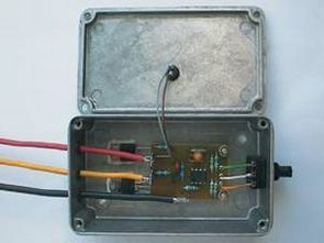
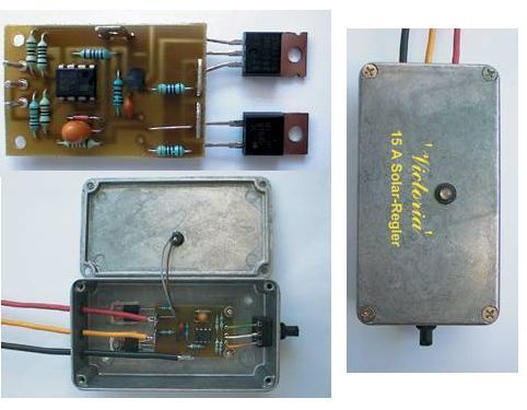
This circuit is housed in a cast housing. The power transistor T2 and the Schottky diode D3 are mounted insulated in the housing for heat dissipation. The assembled circuit board of the controller without potentiometer and LED
This controller is designed for solar systems up to 15 amps. If larger currents are to be charged, the cast housing should be screwed to a heat sink. Transistor T2 and isolation diode D3 should be replaced with more powerful types.
If several solar modules are to be connected in parallel, a separate isolation diode should be used for each module. If one or more modules are shaded, these generators will consume some of the power from the others that are not shaded. Additional diodes are required to prevent this loss.
The Schottky diode MBR 1645, which is already used in the controller, is very suitable as an isolation diode between D1 and D4 in the block diagram.
Şifre-Pass: 320volt.com
Publication date: 2011/06/10 Tags: power electronic projects
100W Amplifier Circuit LYNX PCB
LYNX amp driver stage counted output transistors by increasing the number 500w, ….. 1000w amp circuits is done only on the drive slightest changes happening LYNX mini-project 2 power transistors used accordingly in the output power 100w noise THD rate is very low (0.005) PCB design has been excellent
NPN power transistors: 2SC5200 instead used MJL21194 PNP: 2SA1943 used instead MJL21193 working voltage +-40v