14.4V Charger lead acid batteries, which are discussed here, are among those easier. Nevertheless, it is complemented by a series of functions that inform us about state in which the battery is being charged. I chose battery charger, which follows the charging characteristics for U. This type of charging is advantageous to use a monolithic integrated voltage stabilizers LM350T.
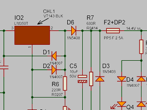
LM350T Battery Charder Circuit Schematic

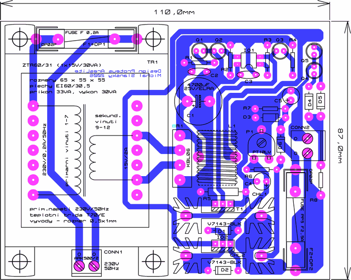
14.4V Charger with proper installation works the first connection, it should light up LED Q1 and Q2. Before the recovery Set the trimmer P1 to the middle position. To try switching function LED Q2 and Q3 Plug in the charger output test resistor of value 100Ω/5W, charger should flow at current 150mA, LED should light up LED LED turn off Q3 and Q2. After disconnecting the test resistor, the LED should switch. Set the trimmer P1 output voltage to 14.4V as accurately as possible using a digital multimeter output voltage should be set with an accuracy of 1% (from 14.25 to 14.55 V). in conclusion test the function of LED Q4 and Q5, remove the fuse F2, connect the battery to polarity (LED Q4), swap the polarity (LED Q5). Returning fuse F2, settings, and recovery is complete. The charger can be placed in an appropriate ventilated enclosures, the construction is completed and ready for use.

The structure is used controllable stabilizer monolithic type in case LM350T TO220, which has good control characteristics, low ripple, large allowable output current and output voltage stability. When you connect a discharged battery to the charger flows thanks to the battery characteristics at a large initial current, which gradually decreases according to the level of the battery. Output voltage (charging), must be set with high accuracy (at least 1%) to 14.4 (charging voltage U = 2.4 V per cell). The initial flow should be in the range of 0.5 to Q 1Q; current depends on the type of battery. Suitable initial charging current climbs adjusted by changing output voltage. Charging current is reduced when the final charge up to 0.005 Q. The battery is charged for a period of about 12 hours, but depends on the charging current at smaller charging current values can take twice as long. the battery is may have connected to a charger and a longer time, the so-called preservative charging when coping self-discharge with a charging voltage (current flowing into the battery approximately equal to 5-10 mA).
14.4V Charger Circuit PCB schematic files download:
FILE DOWNLOAD LINK LIST (in TXT format): LINKS-25340.zip
Publication date: 2013/01/04 Tags: battery charger circuit, power electronic projects
ATmega8 USB Email Notifier Circuit
Market “USB Mail Notifier” ready devices are sold, but in practice, ileginç project also ATmega8 microcontroller and the email account that connects the program’s source code (C + + RAD studiox) or not different projects, mail server and microcontroller communication and so on. would be useful in developing for quite disabled to get the highest yield requirement to prepare an elegant box as in the picture 🙂 author box from the CD sleeve prepared to take the output from laser printers have used the mail icon
14.4V Ladeschaltung Blei-Säure-Batterien LM350T
14.4V Ladegerät Bleiakkus, die hier diskutiert werden, sind unter denen leichter. Es wird jedoch durch eine Reihe von Funktionen ergänzt, die uns über den Ladezustand der Batterie informieren. Ich wählte ein Batterieladegerät, das den Ladecharakteristiken für U folgt. Diese Art des Ladens ist vorteilhaft, um einen monolithisch integrierten Spannungsstabilisator LM350T zu verwenden.
LM350T Batterie Charder Schaltungsschema