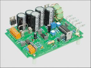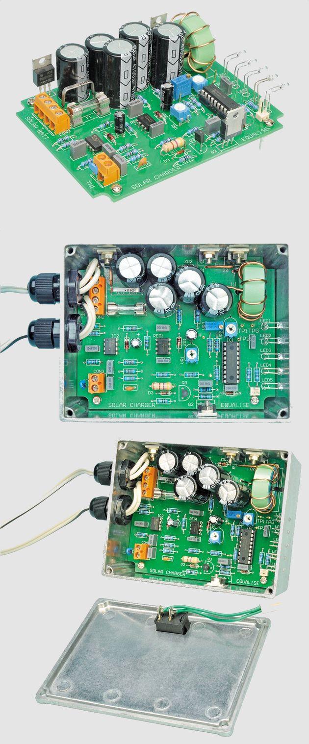
I hope that the interest in evaluating solar energy is quite intense these days, the charging circuit working on the solar panel will be useful to the interested people.
MPPT solar panel charging circuit is based on pic16f88 microcontroller, 12Ah…40Ah Lead Acid, SLA, AGM batteries can be charged, there is a power current table on 12v, information is given according to the battery you will use. Since the charging process is switched, it is fast, there are drawings such as source assebly, hex codes, pcb, schematics, material list, etc. for the circuit.
12V 24V 3-Stage Solar Charge Controller This charge controller is suitable for 12V panels up to 120W and 24V panels up to 240W. It performs Maximum Power Point Tracking (MPPT) and 3-stage battery charging. It works with any 12V panel from 40W to 120W (3.3-10A) and can also be used with 24V solar panels from 80W to 240W, along with a 24V battery.
The Solar Charge Controller is suitable for charging Flooded Lead Acid, Gel Cell (Sealed Lead Acid or SLA) and AGM (Absorbed Glass Mat) type batteries. Ideally, any battery used in the solar panel system should be a “deep discharge” type. Car batteries are not deep discharge types and are not suitable.
MPPT and charge optimization
Given that the solar panel is mounted horizontally, it is most important to collect as much energy from it as possible and this is where the Charge Controller’s MPPT (Maximum Power Point Tracking) comes in.
For a typical solar panel exposed to full sunlight, the maximum voltage is between when the output is open circuited (Voc) and when the output is short circuited (Isc). For a typical 120W 12V panel, Isc is 7.14A and Voc is 21.8V. However, the maximum power output from a 120W panel is 6.74A and 17.8V, which is not very suitable for a lead acid battery.
If we connect this 120W solar panel directly to the battery, the charging current will be about 7.1A at 12V (85.2W), 7.05A at 13V (91.7W) and 7A at 14.4V (101W), which is less than the 120W available from the solar panel at 17.8V.
In contrast, MPPT keeps the solar panel current and voltage at maximum power point while charging the battery, even if the battery voltage is lower than the solar panel voltage.
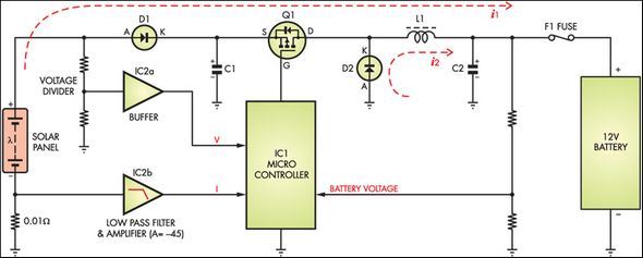
This is done by a smart switch mode step-down voltage converter. To see how this works, see the block diagram below. The current from the solar panel passes through diode D1 and Mosfet Q1. When Q1 is open, current (i1) flows through inductor L1, capacitor C2 and the battery. This stores energy in the magnetic field of the inductor.
The MPPT charging circuit is suitable for 12V panels up to 120W and 24V panels up to 240W. MPPT provides 3-stage battery charging. It works with any 12V panel from 40W to 120W (3.3A – 10A) and can also be used with 24V panels in the range of 80W – 240W with a 24V battery.
The block diagram below shows how the pic16f88 microcontroller monitors the battery and panel voltages and current. It also shows how the switch circuit step-down circuit is arranged for battery charging. When Q1 is on, current (i1) flows through inductor L1 and into capacitor C2 and the battery. When Q1 is off, the stored energy in L1 is fed to the battery through diode D2 (current path i2).


There are many comments about the solar panel mppt battery charger circuit, you can find the answers to the problems you are looking for, below are the answers to frequently asked questions.
DENIS1 says;
I have searched for TL499a everywhere. no no no where can we find it or what can we replace it with. thank you…
gevv says;
I don’t understand why they used TL499a, it is used to feed the microcontroller, it is a 5 volt regulator
of course it works with switching, its efficiency is high, after all they don’t have a problem like finding materials 😀 they are using new integrated circuits
instead you can make a dcdc stepdown regulator with mc34063 or make a regulator with lm317 and set its output to 5 volts
https://320volt.com/online-elektronik-hesaplamalar/lm317-lm338-lm350-hesaplama/
https://320volt.com/online-elektronik-hesaplamalar/mc34063a-hesaplama/
Göktürk says;
Friends, I made 2 of this circuit and one of them has been working without any problems for a year.
-If you can’t find TL499, if you provide the supply of pic with 7805 instead, it works.
-It works without installing thermistor.There are a few things to pay attention to:
Do all operations without PIC plugged in!
-You adjust the VR1 pot so that the pic supply (TP 5V) is 5 volts.
-You measure from the TP1 point, give 15 volts instead of the battery and adjust with the VR3 trimpot until TP1 becomes 4.6875V
-If battery heating is not important, you can also adjust the compensation pot randomly.-TP4 is left so that a relay or something can be connected to disable the loads when the battery voltage exceeds 15 volts and drops below 11.5 volts.
When you connect the circuit and apply electricity:
First, the Bulk LED turns on. High current charge is applied to the battery. When the battery voltage exceeds 12.45 volts, the bulk goes off and the absorption LED turns on. At this stage, a constant voltage is applied to the battery (14.4 volts). When the current drawn by the battery decreases, it passes to the third stage, the float stage, and the voltage applied to the battery drops to 13.5 volts. It stays like this forever. (or until the sun goes down 🙂 )
The equalization switch should normally be closed. When the battery loses its charge capacity, equalization is done by opening the covers to return it to normal. In this position, the charge is increased to 15.84 volts. attention, it is dangerous.
Greetings..
Source: http://www.siliconchip.com.au/cms/A_112335/article.html
Şifre-Pass: 320volt.com
Publication date: 2011/03/14 Tags: battery charger circuit, pic16f88 projects, power electronic projects
15V Symmetrical Power Supply Circuit 7815 7915
78XX and 79XX negative positive regulator ICs, you can easily supply circuit with the series regulator circuits. This circuit gives a nice symmetrical +-15v output printed circuit desing there is a list of the material scope of the pcb, etc. shared images of the schema.