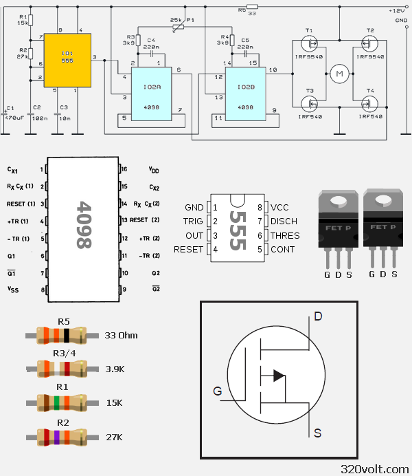
You can see in the diagram 100w motor control circuit with DC +12 V circuit. HCF4098 is provided by the engine control circuit . Cd4098 inside the double precision has a monostable multivibrator . ( I02 and I02B ) Device for application of a voltage limitation that can be reset and re-triggered provides webpages . RX and CX external resistor , a capacitor can be adjusted with an external timing control is provided. RX and CX values Q and Q ‘ outputs and adjusts the pulse width are independent of each other . R5 is a resistor divider .
H Bridge 100W motor drive circuit diagram ;

Timer I01 , I02 and generates trigger signal for I02B multivibrator , the frequency width F = ( R1 + R2 ) * has the formula C2 . For DC motors , I02 and I02B multivibrator output is obtained from the two signals which have the same width , T1, T2 ( p -channel) , and T3 and T4 ( n -channel) MOSFET with the DC motor takes terslenerek . P1 potentiometer allows the DC motor speed control .
Publication date: 2012/02/01 Tags: motor control circuit, motor driver circuit, simple circuit projects
FT232RL USB Multi Converter Circuit
FT232RL integrated USB port using the RS232 serial conversion can be done also RS485 and UART converter is done in this circuit all in one single printed circuit on the PCB layout is also very stylish been unilaterally particular microcontroller projects also will be useful tool .. Also FT232RL manufacturer’s instructions (Future Technology Devices International) prepared “mprog” (mprog EEPROM Programming Utility) with various EEPROM program is said that this circuit http://www.ftdichip.com/support/utilities.htm#mprog