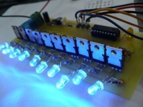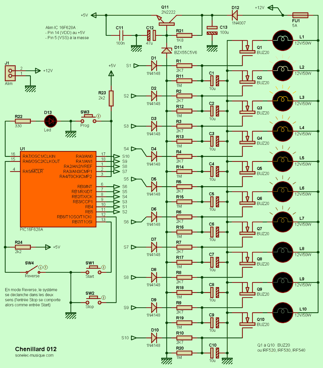
Effect circuit pic16f628 microcontroller based pic16f628a outputs powered by BUZ20 mosfets 10 pieces 12volt 60w lamps can be connected (LED was used in the tests) pcb, schematic drawings and source software prepared with Mikro Pascal Pro (.asm, .hex, .mpas, .mpppi) are available.
It provides instant but sequential switching on of approximately ten 12V / 60W low voltage lamps and their gradual and always sequential switching off (but slower). This system is designed to meet the demand of an Internet user who wants to place ten low voltage spotlights in a side street leading to his house with the following process
After a few minutes (assuming the visitor has reached the end of the corridor), each of the spots gradually fades out one after the other, in the same direction of shift, in a “comet tail” style. I could have developed a system based solely on existing components (classic logic), but for reasons of simplicity and speed, I eventually chose a programmable component of the PIC 16F628A type for the ignition management and the extinguishing of the spotlights. The gradual extinguishing of the lamps, although not provided by PWM, would undoubtedly have been possible, but by a simple discharge function of the capacitors. The latter, if neglected, would lead to the sudden disappearance of the spots.

Adjustment of the on or off delay
The time between the activation and extinguishing of each spot can be set separately. Therefore, it is possible to obtain a fast ignition speed and a slow extinguishing speed or vice versa. The Chaser 012 has three operating modes, which you can switch from one to the other using the SW3 / Prog pushbutton:
Mode 1 = Normal mode = power-on mode – Led D13 off.
Mode 2 = Ignition time programming mode – LED D13 is on.
Mode 3 = Off time programming mode – LED D13 is on.
Each new press on SW3 allows you to switch from one mode to another in a cycle.
To change the time interval
0 – It is assumed that the system is in normal use mode (mode 1), LED D13 is off. If this is not the case, press SW3 once or twice to turn off LED D13 or disconnect and restore the system power supply.
1 – Press SW3 / Prog once. LED D13 flashes three times at a speed that corresponds to the lighting speed of the spotlights and then remains on, indicating that the system has entered programming mode.
2 – Press SW1 / Start to increase the ignition delay (and therefore reduce the ignition speed) or press SW2 / Stop to decrease the ignition delay (and therefore increase the ignition speed). Each time SW1 or SW2 is pressed, LED D13 flashes to provide an overview of the selected firing rate.
3 – Press SW3 to return to normal mode, LED D13 will go out.
To change the shutdown time interval
0 – The system is assumed to be in normal operation mode (mode 1), LED D13 is off. If this is not the case, press SW3 once or twice to turn off LED D13, or disconnect and restore the system power supply.
1 – Press SW3 / Prog once. LED D13 flashes three times at a rate that corresponds to the spotlights’ firing rate, and then remains on, indicating that the system has entered programming mode.
2 – Press SW3 / Prog a second time. LED D13 flashes three times at a rate that corresponds to the spotlights’ firing rate, and then remains on, indicating that the system is still in programming mode.
3 – Press SW1 / Start to increase the fade delay (and therefore decrease the fade speed) or press SW2 / Stop to decrease the fade delay (and therefore increase the fade speed). Each time SW1 or SW2 is pressed, LED D13 flashes, giving an overview of the selected fade speed.
4 – Press SW3 to return to normal mode, LED D13 goes out.
Output stage (power stage)
The power output stage consists of ten sets of exactly the same. For example, Output 1 has components D1, R1, R11, C1 and Q1; Output 2 has components D2, R2, R12, C2 and Q2, etc. The resistor R1 and the capacitor C1 determine the turn-on time of the lamp L1 (not to be confused with the time separating the turn-on time of the two lamps, which is fixed to it at the PIC level in the internal program).
The time constant obtained by giving the values given to these components R1 and C1 is low and the lamp turns on quickly, almost instantly. Diode D1 makes it possible to isolate the capacitor from the PIC output, so that when the PIC returns to the low state, the capacitor does not discharge into it as quickly. When the PIC output is open, the diode is blocked. In the low logic state (0 V), the only way the capacitor can find to discharge is through the high-value resistor R11.
Since its discharge is slow, the lamp gradually turns off. We immediately understand that the turn-off time of each lamp depends directly on the value of this capacitor, which can be easily adapted to your personal preferences. The power MOSFET transistors Q1 to Q10 are BUZ20 models (max. voltage at least 80 V or 100 V and max. current at least 8A or 10A). These MOSFET transistors “draw” a ridiculous amount of current on their control legs (gate / gate) and can switch a current of several amperes,
Lamp Effect Circuit Test
Source: http://www.sonelec-musique.com PIC16F628 Lamp Effect Circuit Altenative link:
Şifre-Pass: 320volt.com
Publication date: 2010/05/20 Tags: microchip projects, microcontroller projects, pic16f628 projects
Use ADNS2610 Optical Mouse Sensor PIC18F4550 USB
Adns2610 interesting optical mouse sensor circuit out of the detected motion is displayed on a computer screen. PIC18F4550 USB connection on the circuit board are available.
Normal mouse but sees his job applications were done with PIC and MPLAB file that contains resources for different projects to be developed, it might inspire
Mouse Sensor Circuit
can you please tell me the password to unzip the file LINKS-10385.zip
Hi, pass: 320volt.com