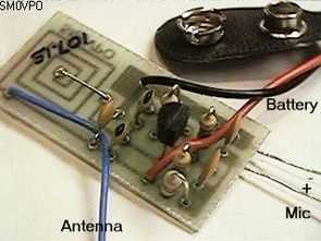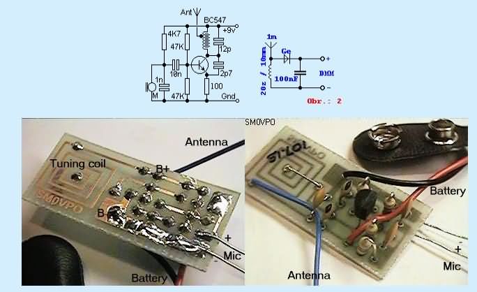
The circuit is made with a very simple antenna coil pcb drawing, there is no need to use an additional coil, there is one transistor in the circuit, I think the circuit will work more efficiently with the equivalent bf series transistor instead of bc547.
A 5 cm wire can be used for the antenna or it can be radio antennas sold in material stores, the fm transmitter circuit works with a 9 volt battery.

The range of this very simple wireless microphone is over 1.5 km. In essence, it is a single transistor LC oscillator that is retuned with the signal provided by the microphone via a transistor-based decoupling capacitor.
The coil is created directly on the printed circuit board, but if you don’t want to do it this way, it is possible to do it with ordinary painted wire. It has about 5 and 1 windings with a diameter of 5 mm. The length of the antenna should not be exaggerated, I used an ordinary wire of about 1 m long, but it is useful to direct it correctly.
For this purpose, I made a simple receiver for the multimeter shown in Figure 2. The multimeter is set to 200mV and the antenna is placed in the expected direction of reception. Then, you turn the transmitter antenna to the maximum voltage on the receiver. Usually I had to slightly tilt the antenna and I tilted it about halfway to the other side, wooden sticks and insulating tape came in handy for this.
The microphone is not very sensitive, so I disconnected the resistor (4k7) that powers the microphone and connected a 10k trimmer to the input against ground. I connected a volkmen to the input of the trimmer and tuned some stations in the AM range on it, so that I could recognize them from others on the radio, or it is nice to play Easy English on the volkmen.
The described transmitter can be used for many things. It can also be used as a basis for wireless control, but be careful! The operation of such a transmitter is prohibited in the Czech Republic and you use it at your own risk.
NOTE: Everything I describe here is true because I made and tested the microphone. I tested the range shown here with an ordinary FM receiver, so if you have a more sensitive receiver, the range is even greater. During the experiments I found something very interesting:
Here the clay is hard and therefore the range is very large, but I also tried in places with soft sandy clay and there the range was much smaller. I did not use a nine-volt battery as a power source, I used a twelve-volt accumulator because of the higher consumption. If you want to reduce the consumption from the source, it is possible to increase the value of the resistor connected to the emitter of the transistor, but this will also reduce the power.
Source: fyzkrouzek.unas.cz FM transmitter Circuit Alternative link:
Şifre-Pass: 320volt.com
Publication date: 2010/07/10 Tags: analog circuits projects
Frequency Adjustable Bass Crossover Circuit
Bass Crossover two op amp circuit (TL072 tl071) integrated circuit based on the symmetrical +15 v-15v working voltage and frequency settings for gain potentiometer has two frequency range 10 … 60Hz
transistor