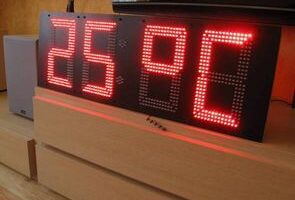
Ledli Saat Termometre Devresi ATmega8 mikrodenetleyici üzerine kurulu yapımı baya zahmetli ama görünümü çok güzel 900 adet led kullanılmış ledler tabelarda ki gibi bir plakaya yerleştirilmiş Atmega8 çıkışlarında 4 adet 74HC574 var çıkışları ise IRF8910PbF (so8 kılıf tek paket iki mosfet smd) mosfet ile güçlendirilmiş pcb düzenlemesi yapılarak piyasada bolca bulunan farklı N-kanal mosfet kullanılabilir.
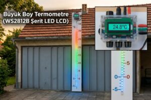
Termometre Saat Devresinde zamanlama için DS1307 saat entegresi kullanılıyor iç ve dış mekan sıcaklık ölçümü içinde iki adet DS18B20 sensör kullanılmış. Projeye ait proteus isis simülasyon, kaynak kod dosyalayı ve ana kartın sprint layout ile hazırlanmış pcb çizimi var.

BÜYÜK SOKAK SAATİ-TERMOMETRE.
Bu yüzden büyük bir LED saat toplamak istedim. Bu tür cihazları oluşturma konusunda hiçbir deneyimim yoktu, bu nedenle tüm tasarım sıfırdan “oluşturuldu” ve onu tamamladığımda, her şeyin farklı şekilde yapılması gerektiğini zaten açıkça biliyordum))).
Saat tahtası 300 mm’ye 900 mm boyutunda olmalıdır, bu, saati yapması gereken nişin boyutudur. LED sayısından tasarruf etmemeye karar verdim, sayıların kalınlığı 3 sıra LED’den oluşuyordu. LED’ler arasındaki mesafe 1 cm’dir. 900 ışık çıktı. Sırada LED seçimi var. Saat sokak için yapıldığından, LED’ler “doğrudan güneşte” bile net bir şekilde görülebilecek şekilde daha parlak seçildi. Kırmızı GNL5013UEC-TL’yi seçin. (4500 mcd). Kırmızı renk en görünür olduğu için seçilmiştir. İleriye baktığımda şunu söyleyeceğim – parlaklıktan çok memnunum! Direkt güneş ışığı altındaki saatler 100-150 metre mesafeden mükemmel bir şekilde okunabilir.
Saat devresi statik göstergeli olmalıdır (yalnızca statikte normal parlaklık elde edebilirsiniz). İşin garibi, internette statik göstergeli hazır bir devre bulamadım. Dinamik bir devre almaya ve statik yapmak için yazmaçları kullanmaya karar verildi. Radiocat web sitesinden DANKO forum üyesinin şemasına karar verdim. Dört kayıt 1533IR37 (74ALS574) yardımıyla dinamiklerden statik aldım ve ardından sahadaki tuşlar aracılığıyla LED’lere geçtim.
(şema tamamlanmadı, ancak ilkenin açık olduğunu düşünüyorum)


there is no enough information to build this. There is NE555 in
schematic diagram but 4 components value that determine pulse freq. are
unknown.
Because ne555 gives EO=clk of 74ls574 chips I need those values? On other hand where is NE555 placed on PCB ?!? Nope…
Also there is no enough info how to connect LED groups and what voltage is required for power supply?
There
is one photo with 5 LED and 1 resistor in series so I was thinking must
make many of those 5+1 groups and then connect them all in parallel for
each segment and 12V
As far as i see those are open drain outputs per each segment so I could make those display by my own configuration.
Anyway what’s up with ne555? On YT video in proteus simulation there is clearly visible “pulse generator ” Thanks