Değişik bir uygulama işin içine bilgisayar girince daha çekiçi oluyor Tarih saat hava durumu rüzgar vb. bir çok bilgiyi bilgisayar ile seri protoköl iletişim kuruyor Kaynak C dili hazırlanmış kod kontrol programı pcb şema dosyaları var.
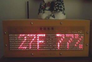
PC’ye RF bağlantılı bir Kayan Ekran
Uzun bir süre, çok sayıda ışıktan bir şey yapmak istedim, ancak mikrodenetleyicilerin her bir ışık için yeterli çıkış pini olmadığında çok sayıda ışığı nasıl bağlayacağımdan emin değildim. İnternetten, bir CRT ekranı çalıştırmak için kullanılan görme hilelerinin aynı kalıcılığının bir ızgara modelindeki LED’lere de uygulanabileceğini öğrendim. Saati ve tarihi gösteren çok basit bir ekranla başladım. Sonra otomatik bir meteoroloji istasyonum olduğunu ve belki de ekrana bir RF bağlantısı aracılığıyla hava durumu verilerini gönderebileceğimi fark ettim. Tamamen üretilmiş baskılı devre kartlarından yapılan bu versiyona ulaşmadan önce iki perfboard/punchboard versiyonu yaptım.
Görme kalıcılığının arkasındaki kavram, parlak bir ışığın çakması durumunda ışığın uzun süre yanıyormuş gibi algılanmasıdır. Işık yeterince hızlı yanıp sönerse (bu ekranda 60Hz), sürekli açık olarak algılanacaktır. Ekran, aynı anda az sayıda ışığın yanmasına izin vermek için bu numarayı kullanır.
Işıklar, bir sütundaki tüm ışıklar pozitif bir terminali ve sıradaki tüm ışıklar negatif bir terminali paylaşacak şekilde bir ızgara düzeninde düzenlenmiştir. Bir ışığı yakmak için gereken tek şey, o ışık için sütun ve sırayı yakmak. Dezavantajı, bir seferde bir sütunun yalnızca bir satırının açık olabilmesi, ancak aynı anda yalnızca az sayıda ışığın açık olması ve az sayıda ışığın kullanılmasıyla ızgara boyunca soldan sağa ve yukarıdan aşağıya döngü yapmasıdır. pin sayısı.
Windows XP çalıştıran bir mini-itx bilgisayar, Lacross hava durumu istasyonumdan bir seri arabirim aracılığıyla hava koşullarını alır, verileri işler ve kaydeder, ardından USB bağlantılı bir RF modülü aracılığıyla evimdeki üç ekrana gönderir. RF modülü donanımı, modülün farklı bir üretici yazılımına sahip olması dışında PINGPONG-CDC ünitem ile aynıdır. BTW, mini-itx bilgisayar da bu web sitesini çalıştırıyor.
DONANIM
Büyük karmaşık panolar oluşturmak çok risklidir. Kartta herhangi bir sorun varsa, bazen pahalı bileşenler üzerlerine lehimlendikten sonra kartın tamamının atılması gerekir. Tek bir büyük panoya sahip olmak yerine, ekran modül panolarına bölünmüştür. Bu modüller, LEDPANEL (ışıklar ve düğmelerin bulunduğu ön panel), LEDDRIVER (satırları ve sütunları açıp kapatan donanım) ve İŞLEMCİ KARTI (RF devresini ve mikrodenetleyiciyi içeren kart)’dır. Kartlardan birinde bir şeyler ters giderse, yalnızca o kartın yeniden tasarlanması veya değiştirilmesi gerekir. İkincil bir bonus, işlemci kartının farklı bir PC bağlantısı için yeniden tasarlanabilmesidir. Bir örnek, maliyet tasarrufu için bir RF bağlantısı yerine bir PC’ye USB bağlantısı olan bir modül olabilir.
Eksiksiz Donanım Ayrıntıları: Şemalar ve Pano Düzenleri ( PCB123 ve Eagle ) Plus BOM
LEDPANEL, LED’leri ve dokunmatik anahtarları içerir. LED’ler kırmızı yüksek yoğunluklu LED’lerdir (Jameco parça no. 333526). LED’ler, 8 sıra ile 48 sütunluk bir ızgarada düzenlenmiştir. Sütunlar, LEDDRIVER modülüne bağlamak için her biri 4 pinli Molex başlığına (parça # 22-23-2041) sahip 4’lü gruplar halinde gruplandırılmıştır. Satırlar ayrıca sütunlarla aynı Molex başlık parça numarasıyla bağlanan 4’lü iki grup halinde gruplandırılır. Anahtarlar 2×2’lik bir ızgarada düzenlenir ve 4 inç Molex başlığı aracılığıyla doğrudan İŞLEMCİ KARTI’na bağlanır. LEDPANEL tamamen açığa çıkar ve #6 vidalarla ahşap muhafazaya sabitlenir.
LEDDRIVER modülü, LEDPANEL’in ayrı ayrı sütunlarını ve satırlarını kontrol eder. Modülün çekirdeği 4 adet 16 bit MCP23S17 SPI port genişleticidir. Genişleticilerden 3’ü sütunları sürer ve genişleticilerden biri satırları sürer. Sütun genişleticiler 150ohm dirençler aracılığıyla bağlanır ve sıra genişletici bir ULN2803A 8 bit darlington dizisi aracılığıyla bağlanır. . LEDDRIVER, İŞLEMCİ kartına bir SPI bağlantısı aracılığıyla bağlanır. LEDDRIVER modülü, arka muhafaza kartının iç yüzüne #6 vidalar ve plastik ayırıcılarla monte edilir.
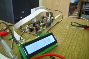
İŞLEMCİ KARTI
İşlemci kartının çekirdeği, 32 MHz’de çalışan bir Microchip PIC18F2620 mikrodenetleyicidir. RF alıcısı, bir LinxTechnologies HP-3 alıcısıdır. PIC18F2620, mikrodenetleyicinin UART’ı üzerinden RF alıcısına ve SPI portu üzerinden LEDDRIVER modülüne bağlanır. İŞLEMCİ KARTI, bileşen tarafı kasanın içinde ve kartın arkası açıkta olacak şekilde kasanın arka panelinin dışına monte edilir. Arka (lehim tarafı) anten, hata ayıklayıcı ve güç jaklarını içerir. Güç, 5v ayarlı bir duvar siğili ile sağlanır.
A Scrolling Display with RF connection to a PC
For a long time, I wanted to make something out of a large array of lights but wasn’t sure how to connect up a large number of them when microcontrollers do not have enough output pins for each light. From the Internet, I learned that the same persistence of vision tricks that are used to make a CRT display work could also be applied to LEDs in a grid pattern. I started with a very simple display that displayed the time and date. Then I realized that I have an automated weather station and maybe I could send weather data to the display from via a RF link. I built two perfboard/punchboard versions before reaching this version which is made fully out of manufactured printed circuit boards.
The concept behind persistence of vision is that if a bright light is flashed the light will be perceived as being lit for a long time. If the light is flashed rapidly enough( 60Hz in this display ), it will be perceived as being constantly on. The display uses this trick to allow a small number of lights to be on at a time.
The lights are arranged in a grid pattern with all the lights in a column sharing a positive terminal and all the lights in a row sharing a negative terminal. All that is required to light a light is to turn on the column and row for that light. The downside is that either only one row of one column may be on at a time, but looping through the grid from left to right and top to bottom with only a small number of lights needing to be on at a time and using a small number of data pins.
A mini-itx PC running Windows XP retrieves the weather conditions from my Lacross weather station via a serial interface, processes and records the data, then sends it to the three displays I have in my house via a USB connected RF module. The RF module hardware is identical to my PINGPONG-CDC unit except the module has a different firmware. BTW, the mini-itx computer also runs this web site.
HARDWAREBuilding large complex boards is very risky. If anything is wrong with the board, the entire board needs to be discarded sometimes after expensive components have been soldered onto them. Instead of have one big board, the display is split into module boards. These modules are the LEDPANEL( front panel with the lights and buttons ), LEDDRIVER( hardware to switch on and off the rows and columns ), and the PROCESSORBOARD( the board that contains the RF circuitry and microcontroller ). If something goes wrong with one of the boards, only that board needs to be redesigned or replaced. A secondary bonus is that the processor board can be redesigned for a different PC connection. An example would be a module with a USB connection to a PC rather then an RF link for cost savings.
The main source code file of the firmware is main.c. As usual, the firmware uses all three priority levels available to the processor. The high priority interrupt is responsible for incrementing the millisecond clock, scanning the keypad for key state changes, and handling new bytes on the RF connection. The low priority interrupt is responsible for scanning the display data bitmap and loading the MCP23S17s depending on the byte that is to be displayed. The main body of the code is responsible for scrolling data and building the bitmaps which are loaded by the low priority interrupt. Double buffering is used to ensure the display state doesn’t change in the middle of a LED scan. As one bitmap is being displayed, another bitmap is being created.
The RF data is a simple fixed length packet. The start of a packet is 4 magic values, followed by the display data, and then ends with checksum. If the magic doesn’t match or the checksum is incorrect, the data is discarded. The RF connection is a simple unidirectional connection that uses a static channel which is configurable from the display unit. The transmitter is not constantly on. It powers off when not updating the display.
The display has 5 different modes of display which are selected randomly. Each mode has a different function in the firmware that is named the same as the mode. These are Static Clock( a static display which displaced the current time ), StaticWeather ( a static display of the outdoor temperature and humidity ), ScrollingClock ( scrolling display of date and time along with the sunrise and sunset time for the day ), ScrollingWeather ( scrolling display of outdoor climate temperature, temperature extremes, humidity, pressure, and rain ), and ScrollingIndoorWeather ( indoor temperature, indoor extreme temperatures, and humidity ).
Kaynak: raccoonrezcats.com/rfdisplay.html (kapalı)


proje dosyaları gözükmüyor ama site ismi werebilirmisiniz??
merhaba rxm-900-hp3 rf modulu nerden temin edebilirim. yardımcı olabilirseniz çok sevinirim [email protected]