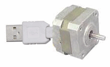
This is an example that demonstration how to control some devices via USB interface.The PC software program with delphi.
Feature :
– CPU PIC18F4550 with full speed USB interface at 48MHz.
– USB 2.0 compliance
– Use on-chip USB driver
– Control 1 stepping motor.
– MPLAB C18 for firmware at USB devices side.
– Delphi 6 for PC Host software.
USB devices side

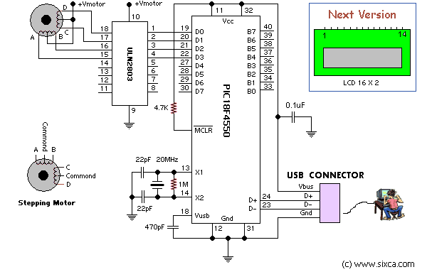
Figure 1. is the schematic for this example.PIC18F4550 is the main devices that communicate with PC and control stepping motor. The power supply came from +5V Vbus for circuit except +Vmotor which must use external power supply that depend on stepping motor requires. If you add more components into circuit that drawn total current more than 250mA you should be use +5V external power supply instead Vbus.Becuase Vbus can supplies current not more than 250mA and don’t forgot to disconnect Vbus out of circuit.
Don’t connect +Vmotor to Vbus.
In this example I drive the stepping motor with 1-phase drive method(A-C-B-D).You may be change for your appropriate application.
PIC18F4550 Control Firmware
The firmware for this example program with MPLAB C18 with USB driver from Microchip. If you need to change or add new command please look at file user.c and use.h in user folder.
stepping motor PC software side
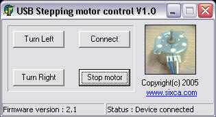
This example program with delphi 6 which modified from C++ wrote by Microchip staff. I have modified the original source code for 3 command for this example : turn left,turn right,Stop motor and connect.For detail of C++ example see in PICDEM™ FS USB User’s Guide and relate files.

The USB driver which use for this project is the Microchip General Purpose USB Windows driver which programming with C/C++ .If you need to program your own USB driver look at this website which have more interest USB driver programming information (www.jungo.com). But, programming USB driver is so hard works.Also,you need to know how dose the OS work.
for more infomation about USB please go to :
http://www.usb.org
http://www.microchip.com
Usb Step Motor control circuit alternative link:
Şifre-Pass: 320volt.com
Publication date: 2008/01/13 Tags: microchip projects, microcontroller projects
Adjustable Power Supply Circuits Archive
In our workshop, to run various circuits, or battery, battery charger that you can use in projects 0.x 0:30 volt power supply circuit that contains a variety of amps I’ve prepared a package. In addition to the professional power supply circuit includes a simple low-power designs.
Circuit in the voltage range of 0.30 volts forces 0.2.5 amps 12:10 amps 10 amp circuits having a little complicated and the cost is high picture circuit a break I’ve done, but a small mistake results can not run error until you find it so much uğraştım afterwards have to pick arrived projects were left unfinished elements with more than be careful teardown
0 0 30 volts 2.5 Amps LM324, BD135, 2N3773
0 30 volts 0 3 Amps TL081, 2N3055
0 0 5 Amps 2N3055 30 volts, LM723, CA3140
0 30 volts 0 5 Amps TIP35C, BD441, 2N3053, BC639, BC547, BC640
0 30 volts 0 10 Amps LM741, LM723, BC557B, BC547B, BD646
0 30 volts 0 10 Amps LM358, CD4011, BC548, BC558, TIP142, 2N3019
Dies ist ein Beispiel, das zeigt, wie einige Geräte über die USB-Schnittstelle gesteuert werden. Das PC-Softwareprogramm mit Delphi.
Merkmal :
– CPU PIC18F4550 mit Full-Speed-USB-Schnittstelle bei 48 MHz.
– USB 2.0-Konformität
– Verwenden Sie einen On-Chip-USB-Treiber
– 1 Schrittmotor ansteuern.
– MPLAB C18 für Firmware auf der Seite der USB-Geräte.
– Delphi 6 für PC Host-Software.
USB-Geräte Seite
Abbildung 1 zeigt den Schaltplan für dieses Beispiel. PIC18F4550 ist das Hauptgerät, das mit dem PC kommuniziert und den Schrittmotor steuert. Die Stromversorgung erfolgte über + 5V Vbus für den Stromkreis mit Ausnahme von + Vmotor, für den eine externe Stromversorgung erforderlich ist, die vom Schrittmotor abhängt. Wenn Sie mehr Komponenten in den Stromkreis einbauen, deren Gesamtstrom mehr als 250 mA beträgt, sollten Sie statt Vbus eine externe + 5-V-Stromversorgung verwenden. Denn Vbus kann einen Strom von nicht mehr als 250 mA liefern und vergisst nicht, Vbus vom Stromkreis zu trennen.
Schließen Sie den + V-Motor nicht an Vbus an.
In diesem Beispiel treibe ich den Schrittmotor mit der 1-Phasen-Antriebsmethode (A-C-B-D) an. Möglicherweise werden Sie für Ihre entsprechende Anwendung geändert.
PIC18F4550 Steuerungsfirmware
Die Firmware für dieses Beispielprogramm mit MPLAB C18 mit USB-Treiber von Microchip. Wenn Sie einen neuen Befehl ändern oder hinzufügen müssen, schauen Sie sich die Datei user.c an und verwenden Sie.h im Benutzerordner.
Software-Seite für Schrittmotor-PC
Dieses Beispielprogramm mit Delphi 6, das von C ++ modifiziert wurde, wurde von Mitarbeitern von Microchip geschrieben. Ich habe den ursprünglichen Quellcode für den Befehl 3 für dieses Beispiel geändert: Links abbiegen, rechts abbiegen, Motor anhalten und verbinden. Ausführliche Informationen zum C ++ – Beispiel finden Sie im PICDEM ™ FS USB-Benutzerhandbuch und in den zugehörigen Dateien.