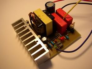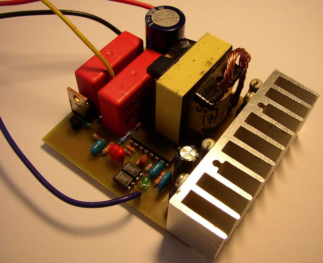
For most people interested in capacitor discharge ignition, the repeatability of DC-CDI is difficult and they have little experience with winding transformers. This design uses an AT-ATX PC power supply transformer for voltage conversion. There is no need to wind the transformer.
The necessary transformer can be obtained from old-style PC power supplies. TL494 or one of its clones (KIA494, KA7500, MB3759, A494, IR3M02, DBL494, S494, NCV494, NTE1729, AZ7500) is used as the control IC.
The transformer usually contains two symmetrical secondary windings for 12V and 5V distribution with the common center of both windings. Thus, the direction of the conversion can be simply reversed. Transformers are always wound for 120 V (and 230 V) distribution and therefore when turning the transformer we get only 150 V, but this is too little for the proper operation of the CDI.
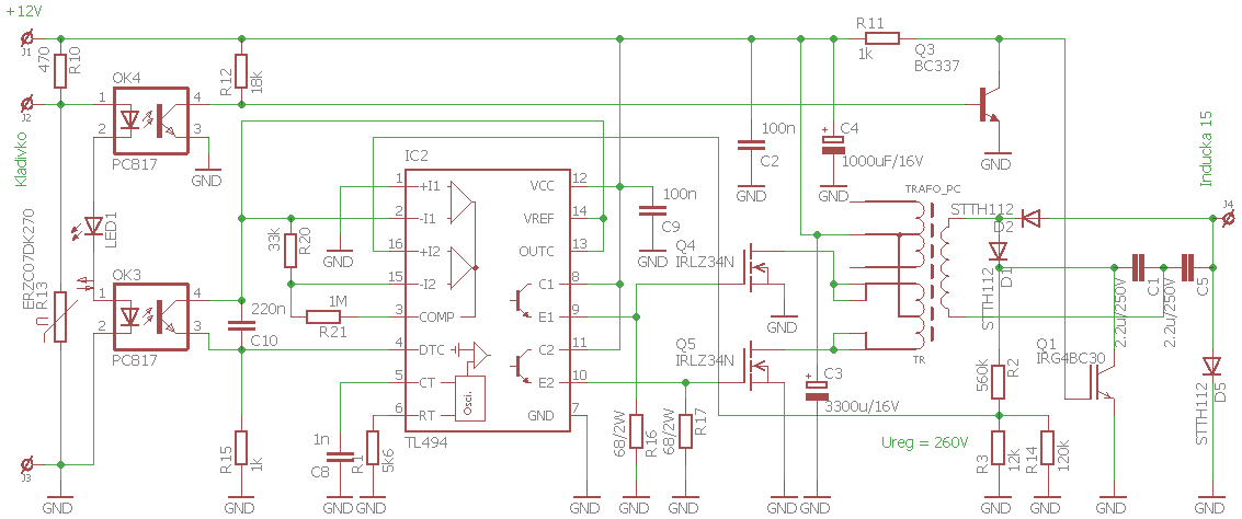
Therefore, the output part contains a voltage doubler D1, D2, C1 and C5. The IGBT transistor Q1 provides the discharge of the capacitance (ignition on the spark plug). The input part contains a pair of isolating PC817 optocouplers, which provide galvanic separation of the converter input from the excitation part of the ignition and form a unit in series with the control LED1. LED1 is connected for optical control of the functionality of the optocouplers.
It is set to 260 V in the circuit. For the simplicity of the power outputs of the TL494, there are resistors R16 and R17 in the circuit, which provide the discharge of the GATE capacitance of the MOSFET transistors and thus ensure a sufficiently fast shutdown of the transistors Q4 and Q5. Resistor R1 sets the optimum frequency of the inverter for the transformer.

We assemble the entire board (including heatsinks) outside the resistors R1, R2 and transistor Q1. Resistor R1 is temporarily replaced with 100k.
A power resistor (at least 10W) with a value of 4k7 is connected between the positive voltage output of the converter (cathode D1) and GND. A voltmeter with a range of more than 300V is connected between the terminals of the power resistor, and a current meter is connected to the power supply wires.
After connecting the voltage source (a sufficiently powerful stabilized 12V source or a charged 12V battery), the trimmer sets the highest possible voltage at the terminals of the power resistor (should be around 300V) with the lowest possible current consumption. After finding the optimum resistance value, the willingness of the source to work should be tested by repeatedly disconnecting and connecting the power supply, while monitoring the constancy of the output voltage and input current.
If the converter starts up at the specified frequency, the trimmer is removed and its resistance is measured and replaced with a fixed resistor to the nearest value, while the reliability of the converter voltage increase is re-tested. It is recommended to test the characteristics at low voltages of around 10 V, as well as at voltages close to the gas outlet of the accumulator, i.e. 14.4 V.
Then the resistor R2 is installed, the output voltage when turning on the inverter should stabilize around 260 V. The change in the output voltage can be changed by changing the values of resistors R2, R3 and R14 (only R14 is used for fine-tuning the output voltage).
Now the power resistor can be removed and the transistor Q1 can be installed. After connecting the supply voltage, the consumption should be negligible, so it should be tested that Q1 is not damaged and does not block the output of the inverter with a short circuit.
The CDI can be used on both single-cylinder and double-cylinder engines. If it is used to ignite a two-cylinder engine, a two-terminal ignition coil is connected to the CDI output, which is connected to both spark plugs. The ignition control is then established so that the ignition will fire at both top and bottom dead center in each cylinder.
Capacitor discharge ignition (CDI) or thyristor ignition is a type of automotive electronic ignition system commonly used in outboard motors, motorcycles, lawn mowers, chainsaws, small engines, turbine-powered aircraft, and some cars. It was originally developed to overcome the long charging times associated with the high-inductance coils used in inductive discharge ignition (IDI) systems and to make the ignition system more suitable for high engine speeds (for small engines, racing engines, and rotary engines). Capacitive discharge ignition uses a capacitor to discharge current into the ignition coil to fire the spark plugs.

Şifre-Pass: 320volt.com
source: jawa-50.cz/clanek/tyristorove-dc-cdi-zapalovani-v51-6v-12v-trafo-pc-zdroj.html
Publication date: 2024/12/17 Tags: power electronic projects, tl494 circuit
hello!
sorry, my english is bad…i use google-translator 🙂
please tell me, at what maximum RPM can this circuit operate?
I encountered a problem: to charge the output capacitor 1.5uF to ~280v at 11000 RPM, it takes ~4.5ms. Is this circuit capable of charging to ~280v in this time if I increase the total capacity of C1 and C5 to 1.5uF?