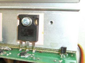
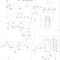
UC3845 Lead–acid Battery SMPS Charger The board is designed as a superior power and a subordinate current regulation, which is powered from the main board. Voltage is sensed using a voltage divider directly on the output switching power supply. Current is sensed by current transformer TR2
and further streamed diode D20, and subsequently converted into voltage insulators on the
voltage. Using a 3-pole switch, you can choose the size of the voltage regulation. Whereupon the position of the the left corresponds to the value of 7.2 V for battery motorcycle batteries with nominal voltage of 6V and position to the right corresponds to the value of 14.4 V for battery cars by nominal the value of 12V.
Switchmode Charger SMPS Schematic
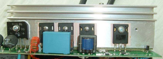
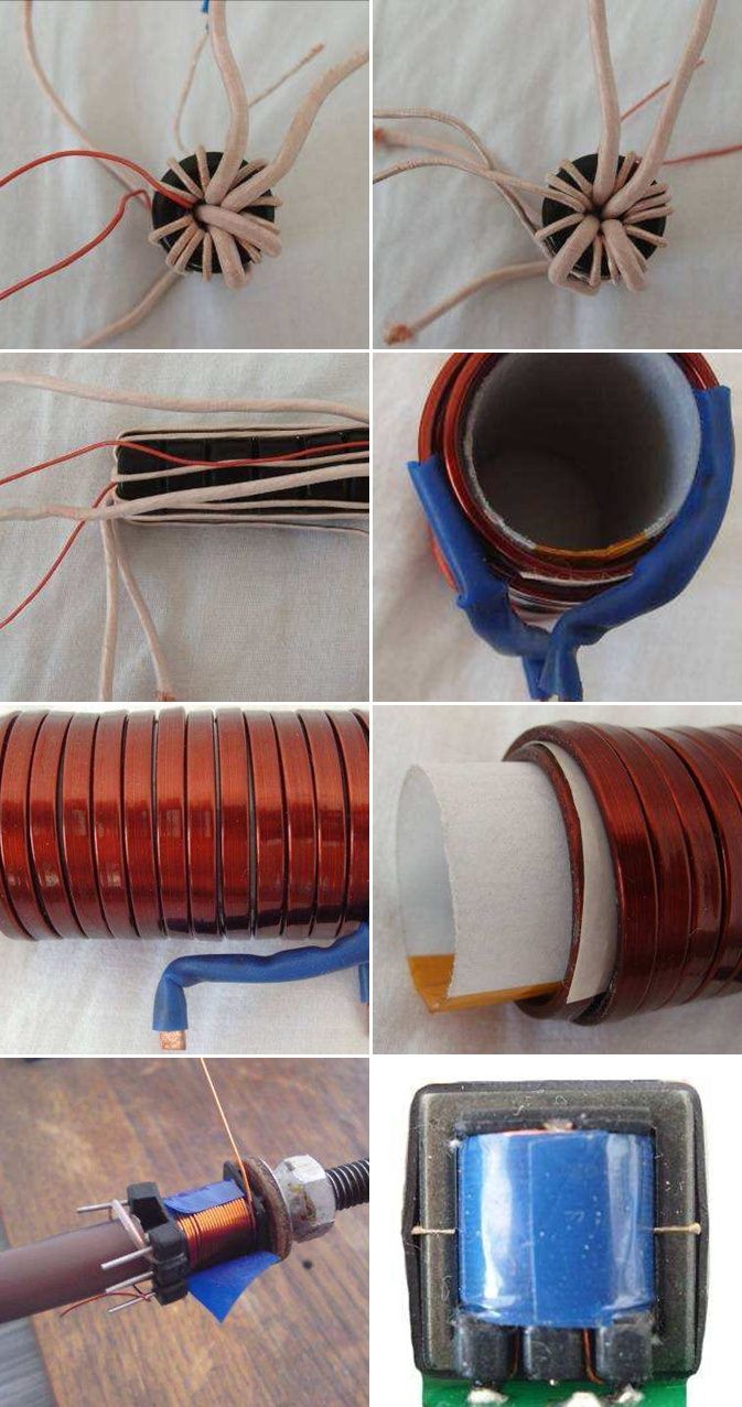
Logarithmic LM3914 Bargraph shows the size of the Charging current. 10 segments bargraph it is divided in the following manner 1, 2, 4, 6, 8, 12, 18, 25, 35, 50 And. Four pole big switch here is for reducing the size of the stream from left to right 0.5 A, 5A, 10A, 50A. On the board of the regulator is also a circuit the relay controlling the fans. The length of the the run-down of the fans is dependent on the load m current. Lead-acid batteries are very often used as a secondary, backup source. Among their main advantages include that they have an affordable price, reliability and the necessary properties. The battery is composed of cells connected in series. Very often involved in a series of 3 or 6 cells – battery is 6V or 12V. Manufacturers is on the market very often supplied in capacities ranging from a few Ah after 240Ah. Articles are composed of the plates (called the electrodes), which are immersed in the electrolyte. The electrolyte in the article it is formed by diluted sulphuric acid. minimum voltage.
![]() SMPS Battery charger circuit pcb schematic all files alternative links:
SMPS Battery charger circuit pcb schematic all files alternative links:
FILE DOWNLOAD LINK LIST (in TXT format): LINKS-25695.zip
Publication date: 2016/06/18 Tags: battery charger circuit, power electronic projects, smps circuits, smps projects, smps schematic
dsPIC30F2010 PWM Motor Driver Circuit DRV8402
DRV8402 Motor Driver Circuit The main component is the microcontroller dsPIC30F2010, who for its activities needs outside of the power supply voltage also a source of accurate clock pulses. In order to achieve the speed of 30 MIPs, we had to calculate the speed of the desired crystal. Each instruction takes four bars of the hourly pulse and when using the multipliers impulses 16x PLL we get a crystal about the size of 7,3728 MHz. According to the datasheet of the processor is needed to connect to the input of the crystal two capacitors.
Schaltnetzteil Blei–Säure Batterie Ladegerät UC3845 SMPS 12V 6V 50A
UC3845 Blei–Säure Batterie SMPS Ladegerät Das board ist konzipiert als eine überlegene Leistung und eine unterlagerte Stromregelung, angetrieben wird es von der Hauptplatine. Spannung spürte einen Spannungsteiler direkt am Ausgang Schaltnetzteil. Aktuelle empfunden von Stromwandlers TR2 und weiter gestreamt diode D20 und anschließend umgewandelt in eine elektrische Spannung Isolatoren auf dem
Spannung. Über eine 3-polige Schalter können Sie wählen, die Größe der Spannungsregelung. Woraufhin die position der linken entspricht dem Wert von 7.2 V, für Batterie-Motorrad-Batterien mit Nennspannung von 6V und position nach rechts entspricht dem Wert von 14,4 V für Akku-Autos von nominal den Wert von 12V.