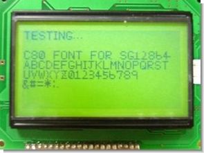
Font libraries and library control done. SG12232 was previously processed by an area twice as long vertically. This module memory control LSI and the instinctive power of the LCD can be easily controlled outside of the control IC without having to connect directly to a microcontroller. Apps can be applied to a variety of shapes, so you can’t just show fonts.
LSI control The LCD module is already built in and the memory can be easily checked as specified in the datasheet. First there is a view on the internal memory module, 0.1 is the display of the data written to that memory in a dot. The datasheet is the address of the horizontal column address, the address is called the vertical line. Set 8 data lines, 0.1 and I/D, E, R/W data lines for you and I will send a command to write an 8-page address to the column specified as 8 bits.
The basic part of SG12232 does not change slightly different from the command system. However, how can data be manipulated as a set of fonts and shapes are the same.

4 This pin is used to distinguish or display data or send commands. Data is displayed in H, L and sends control commands.
15 Enable CS1 Chip, it is pin on left side of LCD. This module is SG12864 controlled area only divided left and right in the middle of the LCD, if you want to control the pin is H to the left half.
16 The pin to enable the CS2 Chip is the right half of the LCD. CS1 uses the same.
6 East This is the drop pin (H to L) or reads and writes data. This was a bit of a challenge when writing a control program.
5 R / W E route with a pin and then specify whether to perform or write. Lead H, L can be specified in light.
7 – 14 command data is the command specified as eight pins. Now unlike LCD, you only control 8-bit mode instead of 4-bit mode. Set the pin command and view the data.
17 RES L takes you to reset the LCD module. Power, except you need something that you can supplement with a direct connection to Vcc.
Particular attention needs to be paid to some contrast wiring. Normally Vcc, if the GND constant resistor is connected to the 1.3-half second input, the second contrast, LCD power relationship and GND driver No. Connected to 1.3 numbers of 18 fixed resistors.
Control method Flow control is as follows.
1. To set the display to pin.
2. Chip selection (CS1, CS2 to choose as needed)
3. A few commands to set the standby. (Wait later)
4. H in both chip selection and reverse command. Wait for a few µS. (Step 3 is reversed. The data is intact.)
5. Clear Data (temporary).
Graphic LCD Module Library for SG12864AS CCS C Compiler download:
Şifre-Pass: 320volt.com
Publication date: 2009/01/23 Tags: ccs c examples, microchip projects, microcontroller projects
Visual Basic DS1621 Two Channels PC Thermometer Circuit
Without using a microcontroller with two DS1621 thermometer circuit further programs and source code in Visual Basic 5 has been prepared by the program data in the text file is a fan circuit with the computer is communicating over RS232 port
DS1621 pc thermometer
So cool you can even measure it!
This incredibly simple thermometer plugs on any free serial port. Does not make use of any programmable components as microcontrollers. It gives temperature readings accurate to 0.5°C with no calibration. It’s cheap, so I’ve put one on any PC I use. And it is so nice to have the temperature shown on the Windows taskbar, that a million friends asked me to build one!
Build yourself an accurate thermometer
gracias por la librería, pero falta la contraseña
contraseña: 320volt.com