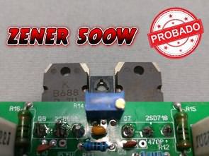
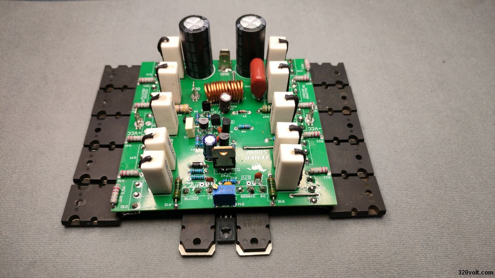
8-OHM RMS 100W Amplifier ZENER’s 500W version. Semi-complementary ZENER amplifier, the sound is very clean and there is no pop sound at the opening. As long as you make it with original and quality components, you can use it for heavy sounding jobs. One of the biggest advantages of this amplifier with differential torque regulation is its high stability.
The first stage of the amplifier has a pair of transistors in a configuration called differential pair. They are driven by a zener diode that can be between 18 and 24 Volts. This keeps the voltage reaching this first amplifier stage constant. It can work with a minimum of 4 ohm speakers. 10 output transistors are used to obtain 500W power. (5X2SC5200, 5X2SA1943)
WARNING! The cost of the project is relatively high. Therefore, your knowledge must be at the same level to understand the project, otherwise you may fail and lose a large amount of money. Therefore, if you are just starting out, I recommend you to start with less complicated and cheaper projects
ATTENTION 500W Amplifier circuit works with high voltage, be careful, pay attention to capacitor connections, if you connect + – poles in reverse, there may be big explosions at high voltage, use Fused Power Line, protective glasses, gloves before operating the circuit
In order to prevent high frequency oscillations, 10pF capacitor was used between the collector and base of 2SCC2229 transistors in the first tests. However, when low values caused distortions due to material quality tolerance etc. problems at high frequencies, 100pF capacitor was used as the most suitable value as a result of the tests.
The function of the other two 470pF capacitors is similar, although not as critical. These can be from 470pF to 1nF. 40pF was used in the application. I did not have any problems with these values. Actually, ceramic or lentil capacitors as they are called in the market do not give me confidence, they seem of poor quality. Instead, multi-layer ceramic or the most suitable green rectangular type ones (called metallized polyester film capacitors) would be much better, but they are very hard to find in our market…
500W Amplifier Circuit Diagram

Signal input Capacitor 0.47uF (470nF) polyester capacitor is a signal input decoupling capacitor. Its function is to prevent DC parasitic currents from being introduced through the signal input. It can be from 0.22uF to 4.7uF. It should be noted that the behavior of the amplifier changes depending on the value of this capacitor.
For example, if we use a 0.22uF capacitor (220nF), we will get a very clean opening without “popping” in the amplifier, but there will be a loss of bass, which will make the sound thinner. If we use this capacitor 4.7uF, all frequencies will pass, but we run the risk of hearing an unpleasant “popping” sound at the opening. A 0.47uF capacitor already allows all low frequencies to pass and provides a clean opening. 1uF also works perfectly. If you plan to use a polarized capacitor instead of a non-polarized polyester capacitor, you should place it so that the negative pole is facing the input.
The 2SC1815 Regulator transistor is part of the differential torque regulation stage. Since the Zener diode cannot provide more than 20 milliamps, it is to amplify the current. Since the transistor can conduct more current, it ensures that the voltage that powers the differential pair never drops. The 2SC1815 can be replaced with a higher power transistor such as 2SC945, 2SC2229 or 2SC1573. The important thing is that it is original and its hFE is not too high. The Zener Diode works with a 4.7K 1W limiting resistor. The Zener diode power is 1W. Since the resistor gets a little hot, it is better to raise it and solder it so that it does not touch the board.
Differential pair (common emitter) (Q2 and Q3) These are two PNP A1015 transistors combined with their emitters, which receive the voltage from the regulation stage mentioned above. The base of the first transistor (Q2) receives the audio signal, while the base of the second transistor (Q3) is connected to the speaker output through a resistor. The collectors of both transistors are connected to negative voltage to –Vcc through a pair of 3.3K resistors. In addition, the collector (Q2) passes the signal to the 2SC2229 transistor (Q5) and the Q3 transistor passes the signal to the Q4 transistor. The emitters of the two 2SC2229 transistors are connected to each other.
500W Amplifier Voltage measurements, tests, all the details in the video;
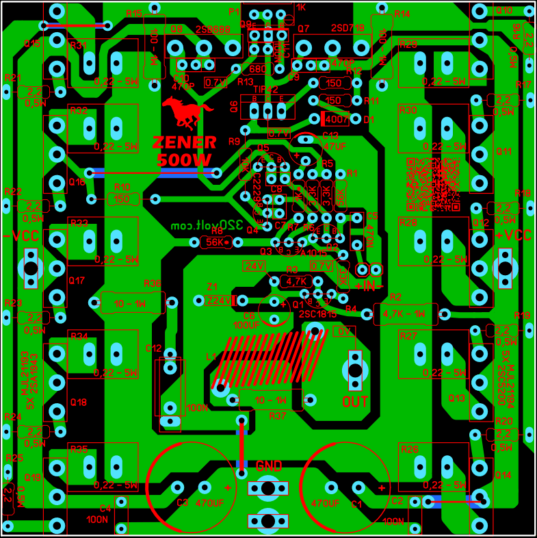
The transistor specifications for the ZENER 100W Amplifier are also valid for 500W;
Make sure that the hFE values of the 2SA1015 transistors with common emitter connection are close to each other. Their hFE should be approximately 170. If the hFE is higher than 180, the 2SA1015 is fake and usually has a BIAS problem. (Comparative; 2SA733)
The gain (hFE) of the 2SC2229 transistors should not be greater than 190. Otherwise, they may be fake. If the 2SC2229 is fake or has high gain, it will damage the output transistors. (Comparative; 2SC1573, 2SC2271, 2SC1921)
The hFE value of the TIP42 transistor can be between 120 and 160. If it is much lower or much higher than this value, it may be fake.
Original power transistors have low gain. It varies from 30 to 180 depending on the model. Measure the hFE of the 2SC5200 and you should get a reading of 80 or less. These provide excellent performance. For the 2SC5200 your hFE should be between 50 and 90.
Amplifier Power Supply
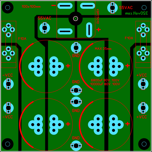
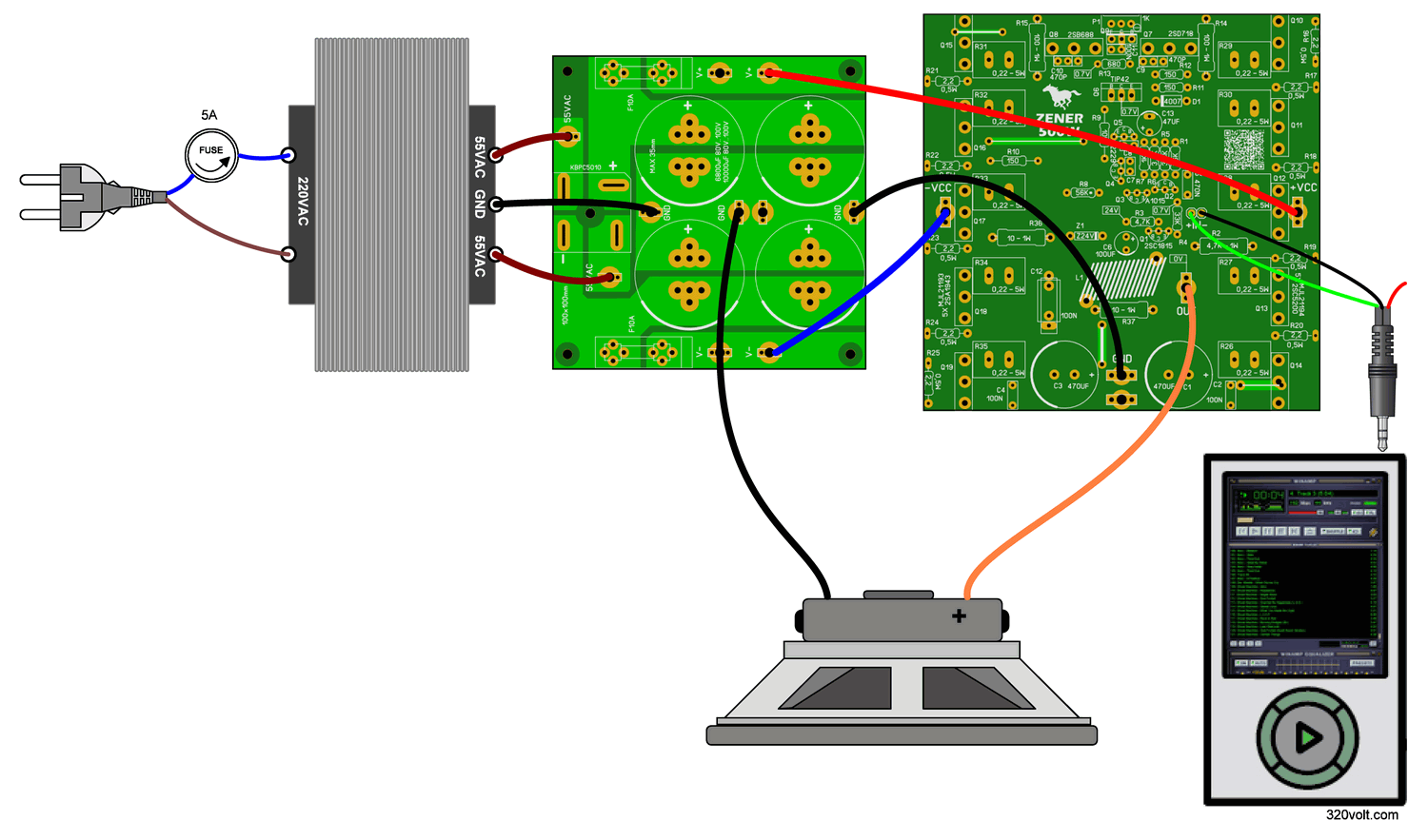
The transformer you will use for symmetrical power shifting should have at least 650W power and its output will be 2X55VAC. Rectifier bridge diode 50 Ampere KBPC5010 Filter capacitors 6800uF 80V…100V or 10000uF can be used. A 5 ampere fuse will be connected to the 200VAC input of the transformer, DC voltage fuses are on the board.
You can use a 8…9mm diameter screwdriver or drill bit to wind the Zobel coil, the wire thickness is 1.2mm and can be wound 12….15 turns. As I mentioned in the video, for the first test, connect a 100W incandescent lamp in series to the 220VAC input of the transformer and a 100-OHM 3…5W resistor in series to the DC lines.
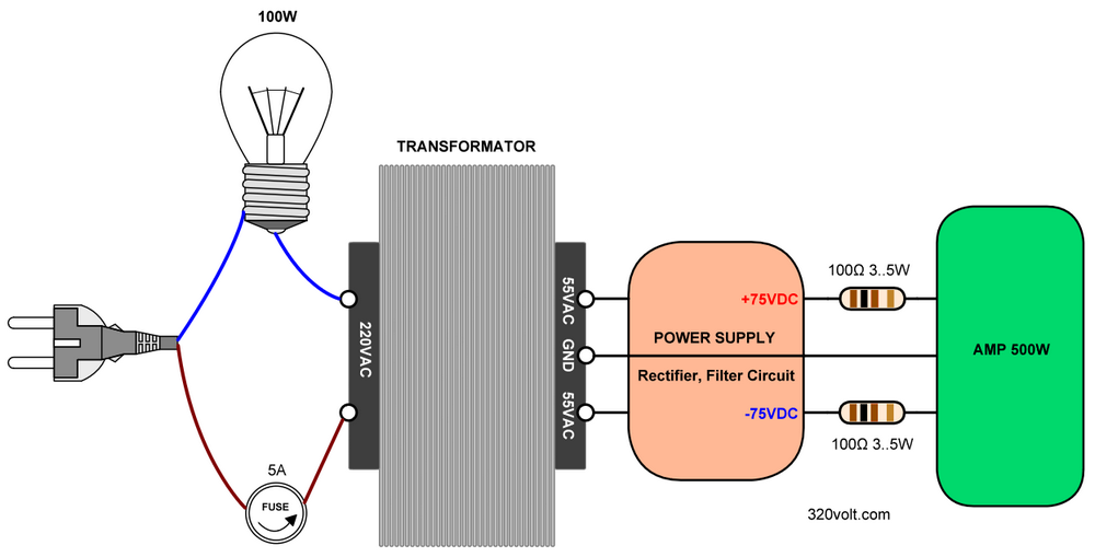
500W Amplifier Wiring Diagram
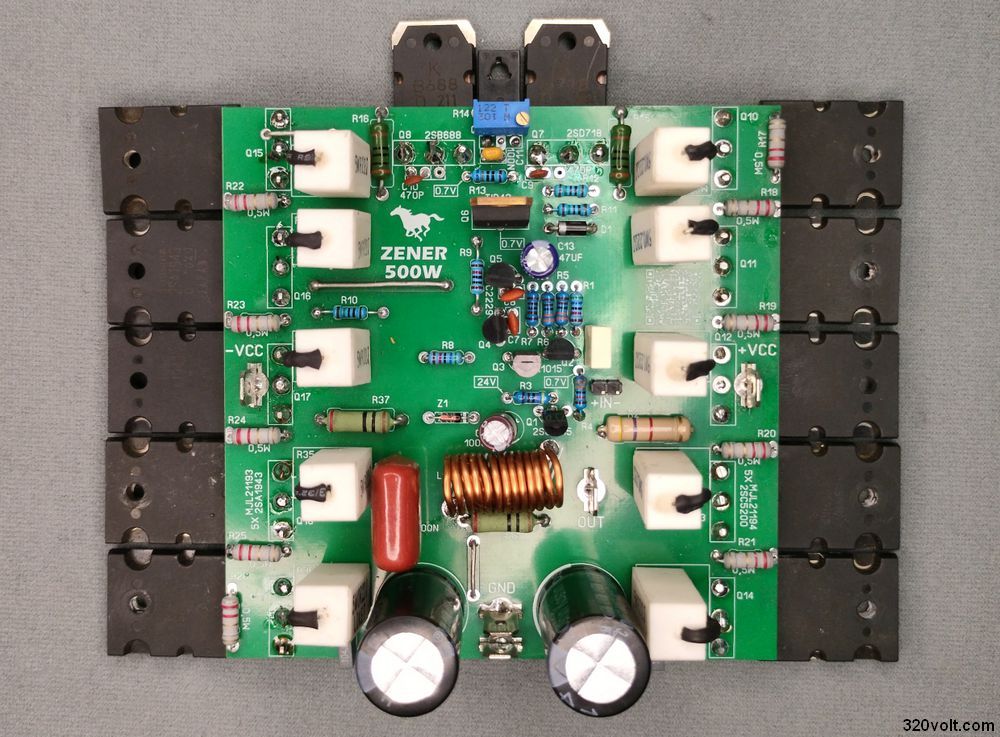
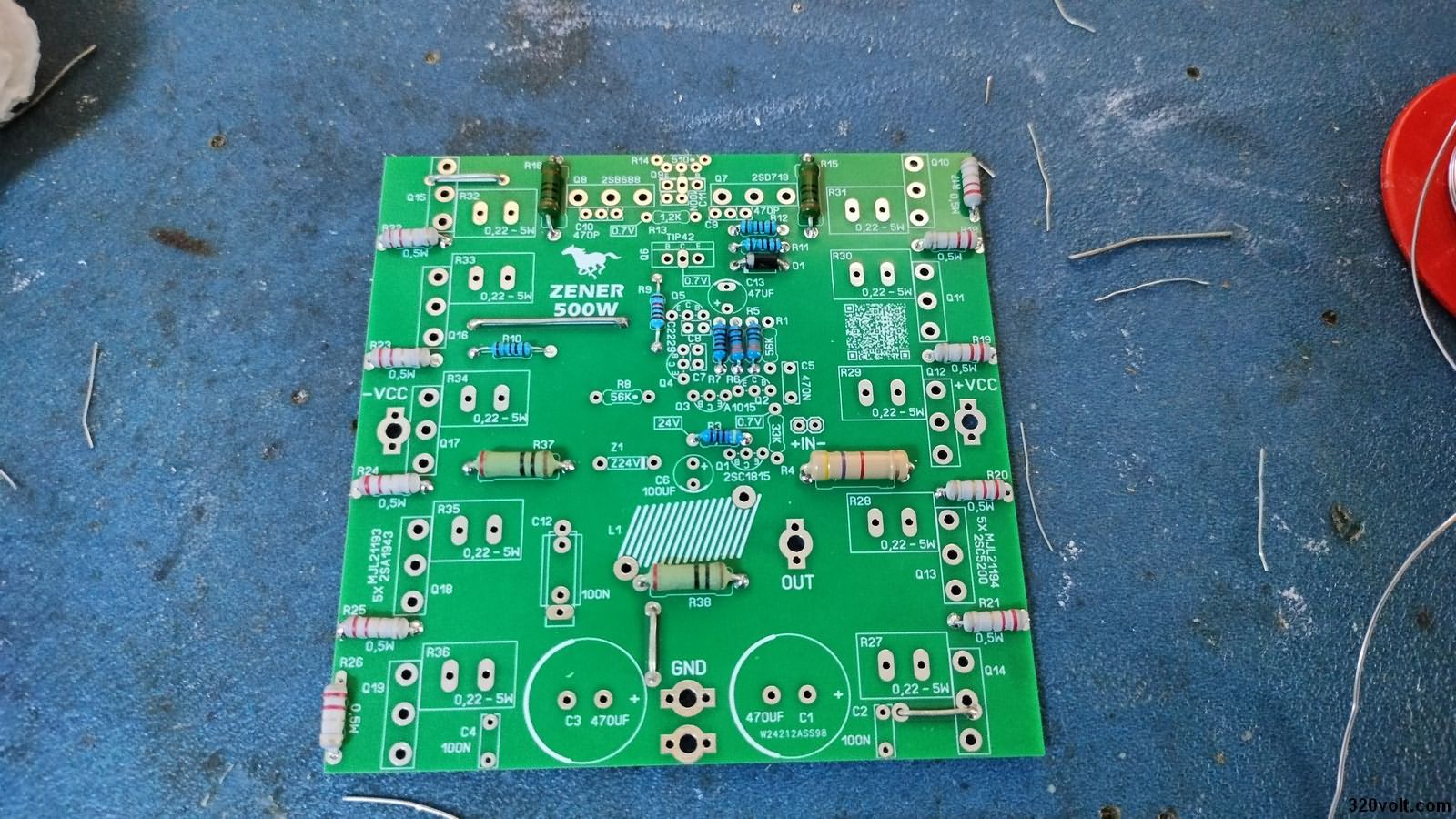
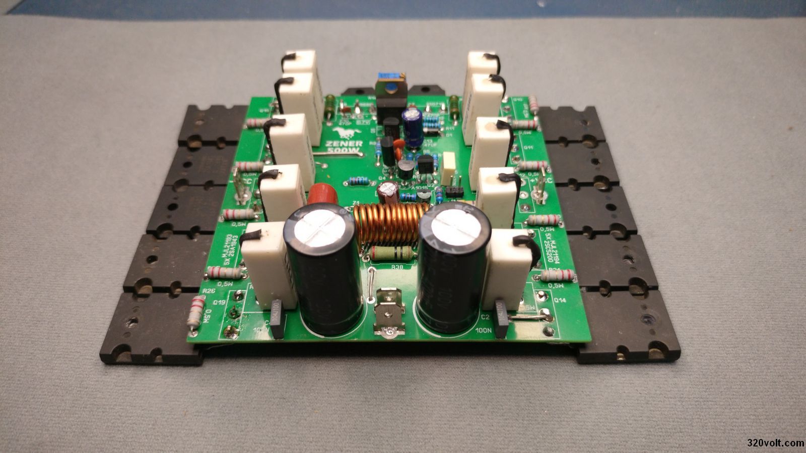
The PCB drawing of the 500W amplifier circuit was made with the Sprint layout 6 program. Dimensions 100x100mm PCB drawings were also prepared for the power supply and speaker protection circuits.
Şifre-Pass: 320volt.com
source: construyasuvideorockola.com
Publication date: 2024/12/17 Tags: audio amplifier circuits, transistor amplifier