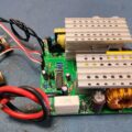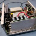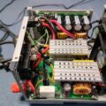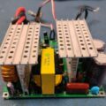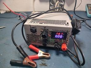
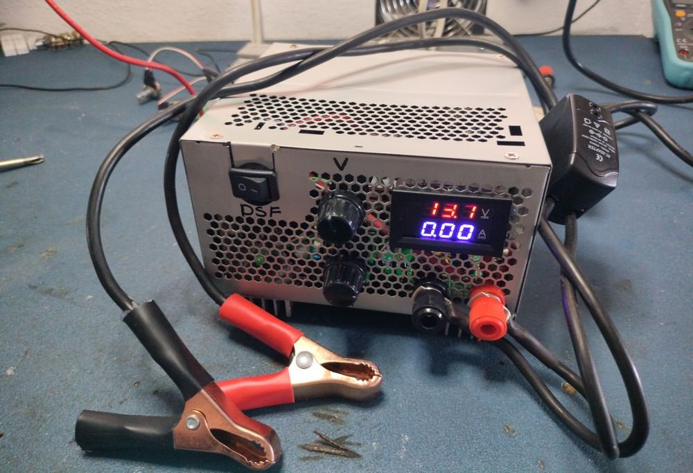
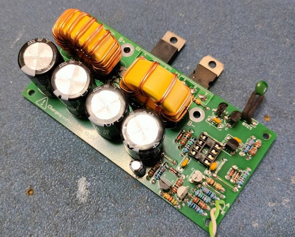
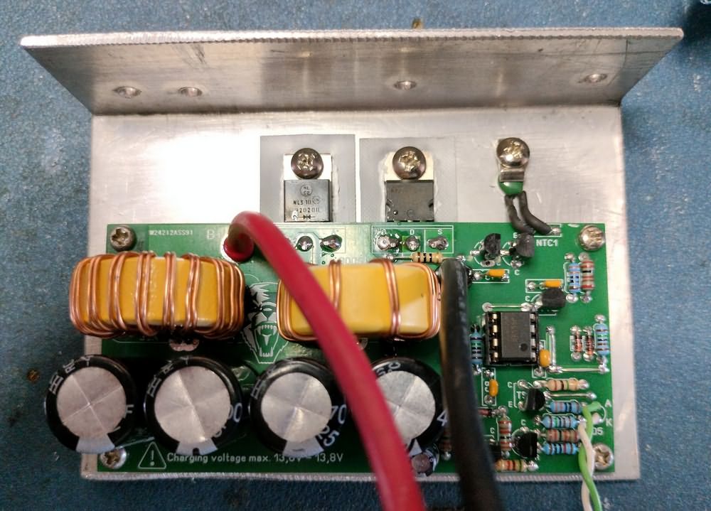
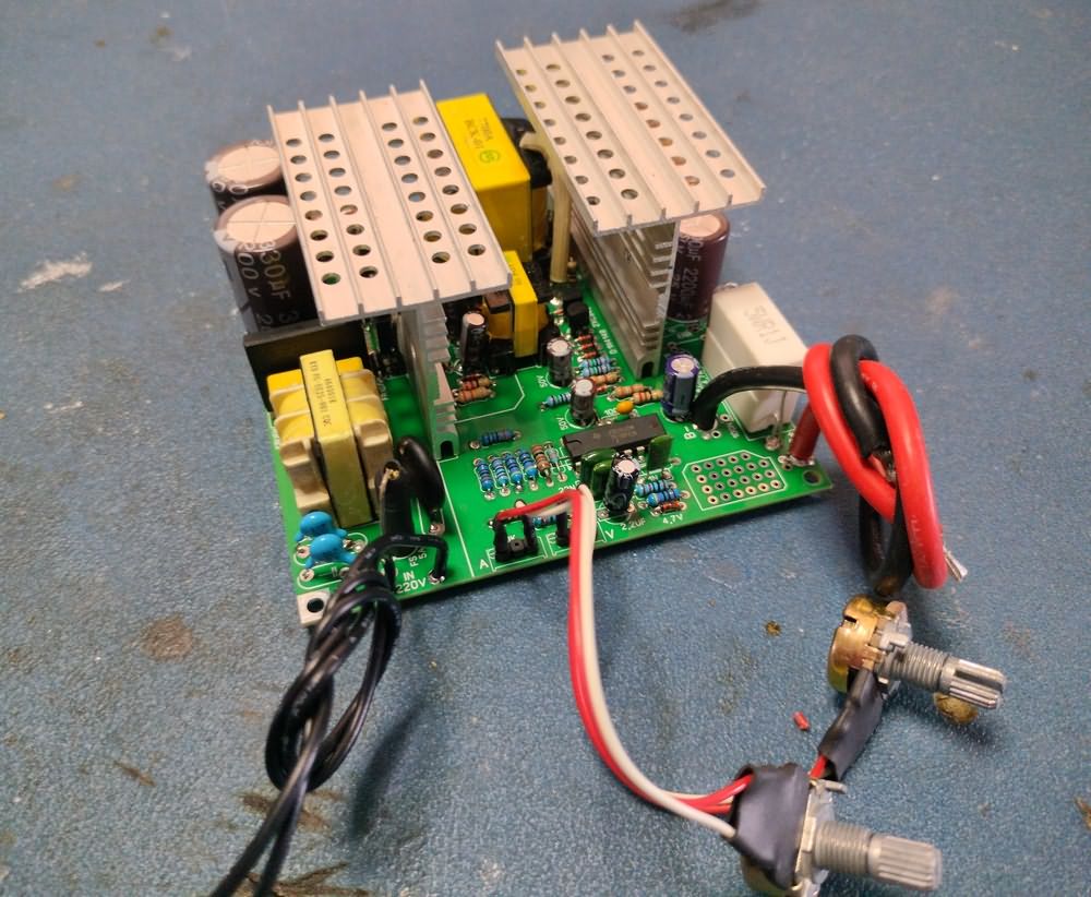
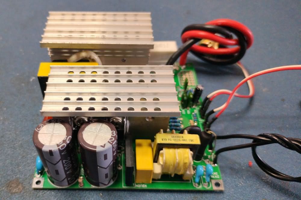
I made a PCB drawing with the power stage of the TL494 control circuit that I shared in the article “Converting a Computer Power Supply to a Battery Charger”. The PCB size is small and light enough to fit in a toolbox with a thick strip cooler that cannot be higher than 10×10 cm, a small fan and a special box. I used the ATX Power supply box. Since the PCB size of the circuit I shared in the article “Advanced Battery Desulfurizer Desulphator Circuit” was large, I redrew it and fit both of them into the ATX PSU box. Both circuits work very well, I tested them for a long time, they should be in a tidy box now.
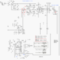
AT-ATX Power supply modified and reverse polarity protection circuit diagrams;

Switching Power Supply Fast Battery Charger
SMPS Battery Charger device also added a protection circuit with mosfets to the output of the charger against reverse connection of the battery, this circuit also provides short circuit protection. Since the charger is current limited, short circuits do not cause problems, the mosfet circuit provides additional protection and also prevents high arc formation. However, the protection circuit clashed with the volt-ammeter module 🙂 I tested the protection circuit, it is a working circuit, there are many people who use it with the TL494 charger circuit that I already applied.
In the tests I did without Volt Ammeter module with mosfet reverse polarity protection, it only went into protection when the batteries were very empty and when I activated the desulfator, I solved the problem by turning it on and off.
When I connect the volt ampere meter module, the protection is activated, when I operate the circuit without the shunt resistor cable and then connect the shunt cable, it works without any problems, when I turn it off and on, the same problem goes into protection. If there is no load, only the current measurement cable is connected, it goes into protection. Since it was certain that the circuit was working, I searched for a long time for the error, changed the parts, tried etc. to no avail.
Then I tried a protection circuit with a mosfet that is triggered according to the voltage, not the current detection, and it had the same problem with the voltampere meter module. . . The module’s measurements are also correct, I tried different modules, the problem continued, finally I canceled the protection and added a relay to the output cable. Sometimes such strange problems find me anyway …
Finally, the reverse polarity protection with a mosfet that works over the current resistance is quite safe even if it is triggered by sudden currents, but since it causes problems with the measurement module, I recommend that you make a relay circuit.
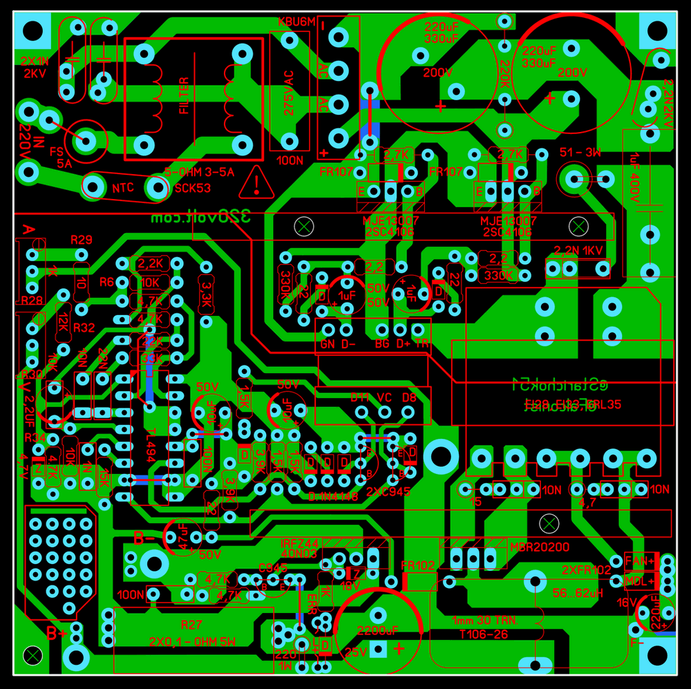
The starting resistors (R18, R19) on the primary stage can be between 220k…330k. I have done a lot of research in the past. The most commonly used value in AT power supplies on the market is 330k. I used 22-ohm instead of 39-ohm resistors R16, R17. This was the value in the main circuit of the transformer I used. You can use the same value according to the card you connected the transformer to. If you don’t have a card, use 39-ohm. I used a potentiometer for current and voltage adjustment. If you are going to leave it at a fixed setting, you can use a multi-turn trimpot on the card.
You should re-wind for the output filter coil or you can buy it ready-made. A value between 56…62uH can be used. If you want to wind it, 30 turns of 1mm wire will be wound on the ring core (T106-26) on the power supply. I had a ready-wound coil, I reduced a few turns and used it.
Note: I used the 12V winding of the output coil directly in the circuits I made before and had no problems.
Batteries over 100AH can be charged with 10 Ampere output power, but the charging time is longer depending on the capacity, and with a few adjustments, 15 amps can be taken from the circuit. In the past, I got 20 amps continuously from the EI33 transformer with TO3P case driver transistors and 30 amp output diode, and I tested it for a long time, but the 12V winding of the transformer gets very hot, and in addition, the transformer needs to be cooled.
For this reason, I say that the circuit will work healthily with a maximum of 15 amps. I haven’t tried it since I’m generally dealing with 45AH…60AH batteries right now, but I don’t think there will be a problem. Also, 20 amps can be taken with the ERL35, which is a little bigger and stronger than the EI33 transformer, but I haven’t tried it, 10 amps is more than enough for now, I’ll try it if needed..
Note: Formulas for current and voltage are given in the diagram. Example max. current calculation; R28 and R29 total: 1010 (ohm) R6 and R27 multiplied: 500 then 1010 divided by 500: 2.02 this result is multiplied by 5 (5V REF): 10.1A. For voltage calculations the result will be multiplied by 3 (3V REF).
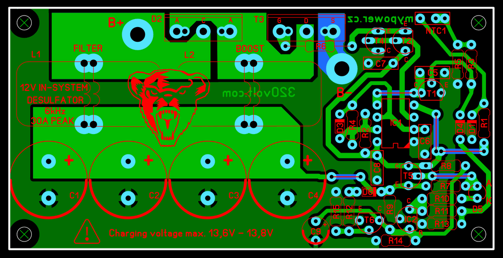
In order to solve the problem of arcing during the connection in the desulfurizer circuit, I made a series switch connection to the plus, minus line, the capacitor connected in parallel to the switch is 10nf 100V. The PCB drawing of the desulfurizer circuit was re-done, its size was reduced (10×5 cm) and the charger fit into the box with vertical mounting.
The aluminum part where I mounted the card is not enough for cooling, there is also a fan, but in addition I mounted small coolers under the case, I would have to make feet for the upgrade anyway, it was a good solution for both cooling and upgrade
Note: The PCB drawing of the two circuits is single-layered, if you are going to print the PCB at home, do not select the C1 layer when printing. Solder filling should be done on power flow paths.
PCB files for TL494 SMPS Charger and High power Desulfator circuit (Sprint Layout 6);
Şifre-Pass: 320volt.com
Publication date: 2024/12/17 Tags: 555 timer circuits, battery charger circuit, power electronic projects, smps circuits, tl494 circuit
