tweeter protection circuit To create this structure led me to the fact that I built speaker system total output of 100W, which are connected the power amplifier 2 x 150W. Even though the manufacturer of height Speaker (TVM) indicates that continuous power is 30W and 120W short, and peaks that are at full excitation amplifiers fall into speaker may be several times higher. However, it may happen that in the belief that own power tweeter, which is connected to an amplifier with a much smaller power to destroy the loudspeakers. This is largely due transistor amplifier, which in overdrive clipping the signal to NF rectangular. This is the cause of the increased content of high frequencies, which i with less power that would not destroy the speaker, blow winding coil speaker.
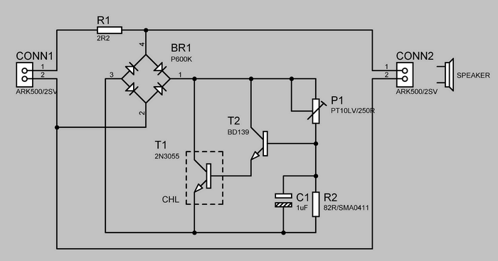
Tweeter Protection Schematic Diagram

Considering that the tweeter is able to utilize only 1% power, for example when we 100W terminals height speaker gets only 1W and 99W rest is radiated heat. it is especially dangerous when starting overdriving the amplifier, which we able to record the human ear. After that, a situation that continues to overdrive will increase, leading to an overburden height speaker and his subsequent destruction. An even worse situation occurs when the amplifier has tone correction and equalization. protection tweeter

In the event that for example the frequency 4kHz raise the gain of 6dB, so the stroke effect doubling performance at this frequency to the higher harmonics is even better path to the tweeter. If you are scared of it as I do, so let into the building mentioned protectors. This protector is mainly applied in speaker, working with high volume, it is here that this structure applies. No wonder that even known manufacturers of power apparatus and equip their PA system speakers similar circuits. And it’s even an advantage, speakers are actively protected against excessive noise.
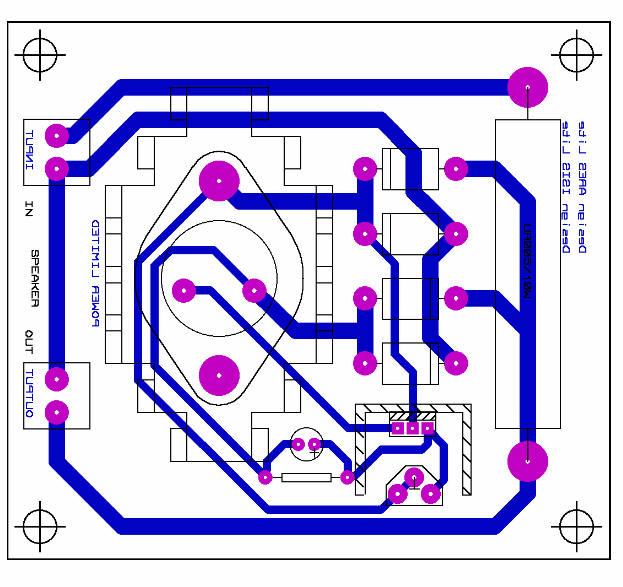
Tweeter Protection PCB circuit schematic all files download:
FILE DOWNLOAD LINK LIST (in TXT format): LINKS-25336.zip
Publication date: 2014/01/06 Tags: audio control circuits
CCS LM35 Temperature Sensor Example with PIC16F877 LCD
PIC16F877 and LM35 Temperature Sensor Application simple CCSC Example PIC16F877 10-bit ADC is be used. Read the ADC result and the information is transferred to the 2X16 LCD temperature value is printed LM35 Digital conversion of the signal undergoes the process of calculating the voltage in mV each 1 degree increase 10mv
Schutz Hochtöner
schutzkreis für den Hochtöner Zu schaffen, diese Struktur führte mich zu der Tatsache, dass ich gebaut, Lautsprecher-system Gesamtleistung von 100W, die im Zusammenhang mit der Endstufe 2 x 150W. Obwohl die Hersteller von Höhe der Lautsprecher (TVM) gibt an, dass eine kontinuierliche Stromversorgung ist 30W und 120W kurz, und peaks, die bei voller Erregung Verstärker fallen in die Lautsprecher um ein Vielfaches höher sein. Allerdings kann es passieren, dass in dem glauben, die eigene macht tweeter, die angeschlossen ist an einen Verstärker mit einer sehr viel kleineren Kraft zum zerstören der Lautsprecher. Dies ist im wesentlichen zurückzuführen transistor-Verstärker, die im overdrive-clipping das signal zum NF rechteckig. Dies ist die Ursache für den erhöhten Gehalt an hohen Frequenzen, die ich mit weniger Energie das wäre nicht zerstören die Lautsprecher, Schlag winding coil-Lautsprecher.