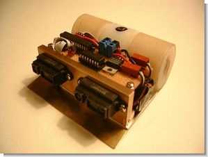
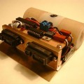
The design of a sumo robot is very nice and the control circuit is based on pic 16f876, the motor driver lm293d, sharp gp2d12 sensors for motion detection, detailed (in English) information about the hardware and software are given in the supplementary files (.doc) and all source CCS C software are available. Suma robot body is very well designed, looks very strong, it has been a body design to be inspired for various robot projects
Mini Sumo Robot
Sumo wrestling is a sport that originated in Japan and typically involves two very large men trying to push each other from a circular ring area. The robotic version of sumo wrestling involves two autonomous robots trying to push each other out of a circular ring. Robotic sumo wrestling is very popular in Japan, with thousands of robots and tens of thousands of spectators in a big competition.
The brain of the Sumo Robot is a Microchip PIC 16F876 programmed in C. FLASH memory is written using a bootloader and the bootloader is originally written to FLASH memory using a Warp-13a programmer. The bootloader uses the chip’s UART hardware to communicate with a PC running Windows XP via a Dallas DS-275 serial interface chip (over serial cable). The development environment is a free text editor called “Crimson Editor” (http://www.crimsoneditor.com) and CCS C (http://www.ccsinfo.com) command line compiler is used. The HEX machine code generated by the C compiler is downloaded to the bootloader using HyperTerminal.
Hardware Features of the PIC Used
A few of the 16F876’s hardware features are used:
• Two-channel hardware pulse width modulation (PWM) is used to provide precise control over the speed of the two motors without using any processor time.
• Four analog-to-digital converters (ADCs) are used to interface with two range finders and two edge detector sensors.
• A 16-bit hardware timer (Timer1) is used to increment a 32-bit integer millisecond counter used for various timing functions.
• In the future, a close range IR sensor will be added to the Seeker II and the required 38 kHz pulse will be driven by Timer0, an 8-bit hardware timer.
• The hardware UART is used both to program the PIC using the bootloader and to run a menu driven debugging system that allows me to test and calibrate motors and sensors.
• EEPROM data is used as a simple log to show state transitions – the current state is stored as the robot changes state. If the robot exhibits strange behavior, I can see what state transitions are causing the behavior, which can be very helpful in debugging. The debug menu provides functions for viewing and clearing EEPROM data.
Electronic
The rest of the electronics in the Seeker II are very simple – 5K pull-up resistor on the MCLR line, a 0.1uf separation capacitor between ground and power on the PIC, a 20 MHz crystal and a pair of 18 pf capacitor crystals. The motors are modified using a Texas Instruments SN754410 quad half-h driver chip, which is basically an amp version of the popular National LM293D h-bridge. Power to the electronics is supplied by a nickel-metal-hydride (NiMh) 9 volt battery and replaced by a National LM2940 5 volt low dropout regulator. Two capacitors (0.47uf and 22uf) are connected to the voltage regulator as suggested in the datasheet. The motors are powered from a second NiMH 9 volt battery. Each battery is individually replaced using a pair of slide switches accessed from the bottom of the case.
For sensors, the robot has two rangefinders and two edge detectors. Rangefinders are Sharp GP2D12 analog distance sensors. Inexpensive, simple to intervene, it gives very accurate results without being affected by the lighting conditions of the environment. Edge detectors are Fairchild QRD-1114 IR sensors. They also filter out most ambient light interference and generally work extremely well.
Software
PIC 16F876 is a very powerful microcontroller. In addition to the hardware features mentioned above, Seeker II’s software is highly advanced. The main control loop is implemented as a formalized finite state machine (FSM). Using an FSM simplifies the code management issues inherited in any complex piece of control software. The currently applicable situations are as follows:
• WAITING_FOR_BUTTON – this is the initial state of the robot after power-on. It basically checks if the start button is pressed and if it is, the current state is changed to PAUSE.
• PAUSE – This situation imposes a 5 second pause, which is a requirement in mini sumo rules.
• START_LOOKING – This is the first motion state where the robot starts searching for the other robot. The current status is immediately set to LOOKING.
• LOOKING – This is the main call state. The robot checks the rangefinder sensors and switches to PUSHING_OBSTACLE when it sees something in any of them. STA if it detects the edge of the ring
Switches to RT_BACKOFF.
• PUSHING_OBSTACLE – This is where the robot takes the opponent into view and homing and pushing. If only one rangefinder sensor can see the opponent, the corresponding (left or right) motor is slowed slightly to spin the robot towards the opponent).
• START_BACKOFF – Here the robot detected an edge and stopped. To ensure no lag and avoid edge-out, the stop behavior is implemented as part of the sensor search in the main loop. This sets the robot to reverse in a straight line.
• BACKOFF – In this state the robot goes back ¾ seconds, then stops and switches to START_LOOKING_AFTER_BACKOFF
• START_LOOKING_AFTER_BACKOFF – Here the robot starts moving forward again after backing up from the edge. The robot makes a sharp turn for half a second and then returns to its normal START_LOOKING state.
PIC16F876 Sumo Robot Project
Sumo wrestling is a sport that originated in Japan, and typically involves two very large men trying to push each other out of a circular ring area. The robotic version of sumo wrestling involves two autonomous robots that try to push each other out a circular ring. Robotic sumo wrestling is very popular in Japan, with thousands of robots and tens of thousands of spectators at a large competition.
In North America, a new form of robotic sumo is starting to gain a following. Started by Bill Harrison (Sine Robotics, http://www.sinerobotics.com), autonomous mini-sumo robots can be simple and inexpensive to build for the beginner, while at the same time providing intense competition for robot builders at a more advanced level. Mini-sumo robots are half the size of regular sumo bots, and compete on a ring that is half the size as well.
The rules are fairly simple: two autonomous robots face off on a ring that is 77cm across, and the first one to touch outside the ring loses. The ring surface is black, and there is a 2.5cm white line around the outside top edge of the ring. The robot has to fit inside a 10cm x 10cm square tube placed vertically over it when it is in the start position on the ring, and it must weigh no more than 500 grams. The robot is not allowed to intentionally damage another robot, and must not damage the ring. The full rules can be found online at http://www.robotgames.com.
There are a number of mini-sumo kits that you can buy off the internet, but I decided that I wanted to come up with something a little different. And so, after a couple tries and a lot of thinking and design work, a new mini-sumo was born. One thing I did not need to think much about was which micro-controller to use – all my robots are controlled by Microchip PIC micro-controllers.
Sumo Robot Hardware Features of the PIC Used
Several of the hardware features of the 16F876 are used, including:
• Two channel hardware pulse width modulation (PWM) is used to provide precise control over the speed of the two motors, without using up any processor time.
• Four analog to digital converters (ADC) are used to interface to two range-finder and two edge-detector sensors.
• One 16 bit hardware timer (Timer1) is used to increment a 32 bit integer millisecond counter, used for various timing functions.
• In the future, a close-range IR sensor will be added to Seeker II, and the 38 kHz pulse required will be driven by Timer0, an 8-bit hardware timer.
• The hardware UART is used both to program the PIC using the bootloader, and also to run a menu-driven debug system that allows me to test and calibrate the motors and sensors.
• The data EEPROM is used as a simple log to show state transitions – as the robot changes state, the current state is stored. If the robot exhibits strange behavior, I can see what state transitions led up to the behavior, which can be a great aid in debugging. The debug menu provides functions to display and erase the data EEPROM.
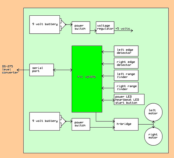
The rest of the electronics in Seeker II are very simple – a 5K pull-up resistor on the MCLR line, a 0.1 uf decoupling capacitor between ground and power on the PIC, a 20 MHz crystal, and a pair of 18 pf capacitors for the crystal. The motors are switched using a Texas Instruments SN754410 quadruple half-h driver chip, which is basically a one-amp version of the popular National LM293D h-bridge. Power to the electronics is provided by a nickel-metal-hydride (NiMh) 9 volt battery, and switched through a National LM2940 5 volt low-dropout regulator. Two capacitors are attached to the voltage regulator as suggested in the data sheet (0.47 uf and 22 uf). Power to the motors is provided from a second NiMh 9 volt battery. Each battery is switched separately using a pair of slide switches accessed from the underside of the chassis.
For sensors, the robot has two range finders and two edge detectors. The range finders are Sharp GP2D12 analog range sensors. They are cheap, simple to interface to, and provide very accurate results without being affected by ambient lighting conditions. The edge detectors are Fairchild QRD-1114 IR sensors. They also filter out most ambient light interference, and in general work exceptionally well.
source: circuitcellar.com/flash2002/Honorable/298-Abstract.htm Sumo Robot Project ccs c source code robot schematic files alternative link
Şifre-Pass: 320volt.com
Publication date: 2009/06/15 Tags: ccs c examples, microchip projects, microcontroller projects, pic16f876 projects
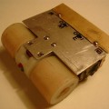
27 MHz Wireless Keyboard SPY Circuit Atmel ATmega64
In an article “Symantec warns: each word or phrase that you enter on the wireless keyboard, can be tracked!” Was called I knew it was true, but such a project would never have thought I’d reached on the web
Circuit else is going on what is written in the wireless keyboard can be sent to computers for most of our tests uses a “microsoft wireless multi media” is done on the keyboard
Wireless Keyboard SPY