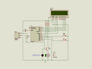
In this circuit, temperature information is obtained by using PIC16F84A microprocessor and DS18B20 temperature sensor. The temperature information obtained is displayed on the 16X2 LCD screen, giving an audible warning when the temperature value specified by the user is exceeded.
It enables the fan to operate until the ambient temperature drops to the desired level. In addition, the temperature value specified by the user is saved in the eeprom, preventing the loss of information in any power cut. The plus (+) and minus (-) buttons allow you to set the temperature level required for the fan to work.
Materials used in the fan control circuit with PIC16F84A and DS18B20 temperature sensors;
1 PIC16F84A microprocessor
1 Piece 16X2 LCD
DS18B20 temperature sensor
1 Piece 1K resistor
3 pieces of 10K resistors
1 Piece 4.7K resistor
1 Piece 330Ω resistor
1 Piece LED diode
1 Piece BC237 transistor
1 Buzzer
1 Piece 4Mhz crystal oscillator
2 x 22pF capacitors
2 buttons
Source Codes
Microprocessor codes of the circuit were written and compiled in MicroCode Studio Plus PIC BASIC PRO compiler. For compiling, your computer must have the PBP246 and MPASM assembly compiler files.
PIC16F84A Fan Control Schematic
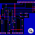
PIC16F84A Fan Control PCB top
PIC16F84A LCD Display Fan Control Circuit proteus isis simulaiton schematic proteus ares PCB and pic16f84 picbasic pro source code files
Şifre-Pass: 320volt.com


LCD Display Counter Circuit with PIC16F84A Picbasic Pro
In this circuit, the PIC16F84A microcontroller and 16X2 digit counter 12 is made using LCD screen. SWITCH button LCD each signal sent from the values of a which provides enhanced. If the RESET button on the LCD allows the values reset.
LCD Display Counter Schematic
What is the zip password?
password for all files: 320volt.com