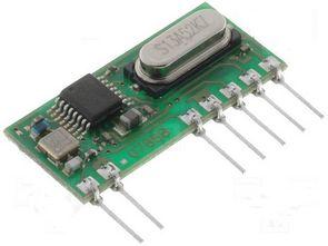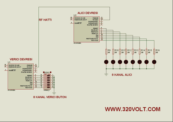
The aim of the application circuit to consolidate the operation of the transmitter and receiver circuits. Our circuit consists of two separate circuit. 1st half 2nd half transmitter receiver circuit. The transmitter circuit 16F628, hibirit transmitter, 4-way dip switch. Receiver circuit 16F628, buyers of hybrid, 4 led.devre our 4 channel RF transmitter and receiver circuit. The number of channels can be increased by hardware and software.
In 150 meters in open space are working smoothly. 50 meters closed area is working smoothly.
The transmitter circuit pull-up resistor for the switch would have to use. 16F628 own pull-up resistances are used in the software. OPTION_REG = 7 Commands we must not add to the program.
RF Transceiver Circuit Test
RF Transceiver proteus isis schematic

4 channel RF applications of sensor data with PIC16F628 picbasic pro code files and isis proteus simulation files:
Şifre-Pass: 320volt.com
Published: 2010/05/01 Tags: microchip projects, microcontroller projects, pic16f628 projects, picbasic pro examples
Free CNC Simulator Program CncSimulator
CNC simulator program seemed very interesting to me dealing with someone who knows the business can resolve an application to the measurements given guess XY, YZ, XZ, according to the information of the 3D simulations show that the CNC applications
CNC Simulator
Hello sir,
May I know the password??
which compiler and MPLAB IDE you used??
Thanks in advance
Hello,
pass: 320volt.com mplab ide not used picbasic used