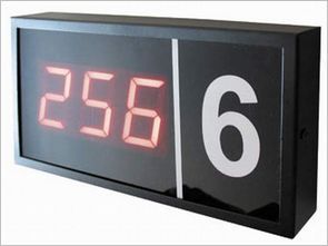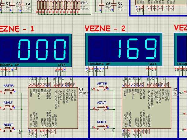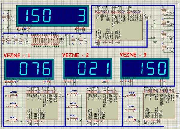
In this article I used in banks and hospitals will give information about the Q-matic s. I’ve done a routing circuit board (main board) and consists of three separate teller. Routing PIC16F877 on board, if the teller did not use pic16f876 in each. Teller as the officer may increase, decrease or can be reset. Every teller has been working with the same logic.

Their value as a teller at regular intervals each orientation is sent to the board. Clipboard routing information from each teller overlook the ordinary. Each of the received data and also shows teller number of their displace. Each display is working with the logic scan.
PIC16F877 Q-matic Circuit Schematic

Each displace the software are as follows; a first rank value, tens and hundreds digit is determined. This value is shown in the display of the first one’s place and then later on they face, including the step sequence is shown, and this is very fast, is difficult to detect with the human eye. We’ll just see on the screen the entire sequence value. This scanning period will normally need to be 14ms. But I’ve adjusted according to the simulation program.
Q-matic Circuit Test
Author Ediz Ağarer – Micro-controller controlled the Q-matic application circuit schematic source code files:
Şifre-Pass: 320volt.com
Published: 2010/06/03 Tags: microchip projects, microcontroller projects
PID Control with PIC18F252 Microcontroller
For speed control of a DC motor in a closed loop PID controller with integrated driver l298d used for motor control applications. PID microprocessor control circuit pic18f252 prepared by the C language source code for the software installed on all the details are flow diagrams
PID Control Circuit