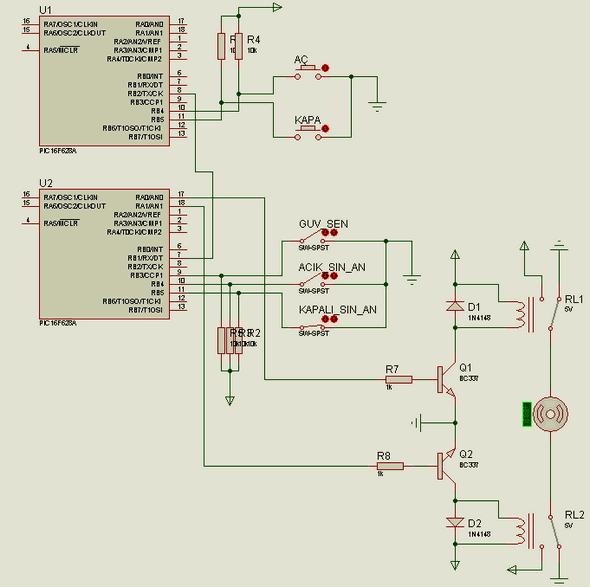
Projects prepared to control the garage door are prepared with Microchip PIC series microcontrollers. In remote controlled garage door control with RF Modules, pic16f628 (C language/udea rf module) is used. In IR infrared garage control, pic16f84 (asm) microcontroller and sharp GP1U52X sensor are used. There are many details in the project prepared especially with asm, it will be useful in 2 applications. Thanks to those who contributed and prepared it.
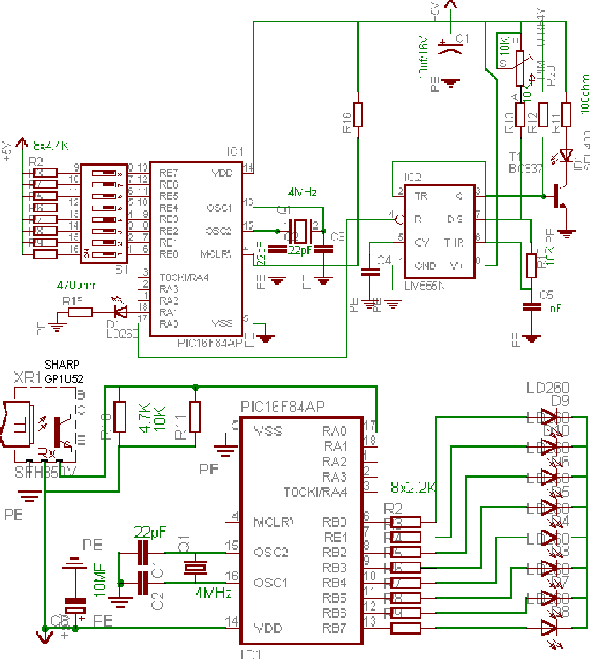
InfraRed (IR) remote control systems use an IR Led diode as a light source and an IR photodiode or transistor as a receiver. As can be seen from the diagram below, our IR remote control system consists of a transmitter and a receiver circuit. In the IR transmitter circuit, radiation is provided in the IR spectrum with an IR Led. The LM555 integrated circuit to which the IR Led is connected is an oscillator in the range of 38…..40 Khz.
This oscillator is modulated by the pic 16f 84 in the transmitter to obtain a 38 khz modulated control signal. You may think why don’t we drive the led directly with the pic, why is 38 khz needed? The simplest explanation for this is to prevent interference from surrounding infrared interference sources. The standard incandescent bulbs we use at home operate as 50 Hz IR sources… If we did not use the 38 khz carrier, a continuous and strong suppression of 50 Hz would prevent us from sending a signal to the receiver.


The GP1U52X IR receiver module from SHARP, which we use in the IR receiver circuit, is a unit that detects the signals coming from the IR remote control on TVs and filters them from the 38 khz carrier and leaves the pure control data… In short, it is not just a single phototransistor… The module contains one IR phototransistor, a 38 khz band-pass filter, an amplifier, and a signal shaper. Its output is a control signal at TTL level.
Don’t be afraid of this module, it is not hard to find because there must be such a module on every IR remote controlled TV. You may not find the same brand or type, but you can use any of them as long as you learn the pin connections. Telefunken’s TK19 module was often on the market with SHARP for a while. The RB0.. RB7 pins of the transmitter circuit are the control pins.
If you connect these pins to the chassis with the help of switches, for example, if the pin you connected on the receiver is RB0 on the transmitter, RB0 on the receiver will also start transmitting. When you release it, the relevant pin will remain transmitting until a new control signal comes to the receiver. While the control signal is going, the LED connected to the RA1 pin will light up.
The circuit should be checked by starting with the transmitter first. Do not replace the transmitter pic and connect pin 4 of the LM555 integrated circuit to +5 volts. In this case, the oscillator constantly produces a signal around 38 kHz. Give +5v to the receiver without connecting the pic. Read the distance between the sharp module pin 1 on the receiver and chassis with a voltmeter.
When the receiver and transmitter are in a position where they see each other, when you give voltage to the transmitter, you should read 0, that is, chassis, and when there is no voltage to the transmitter, you should read +5 volts with the voltmeter on the receiver. If there is no change in the voltmeter as a result of such a check and the voltmeter always stays at +5 volts, give voltage to the transmitter and try to see 0 volts, that is, chassis, on the voltmeter on the receiver by playing with the P1 potentiometer. When you see the chassis, it means that the system can communicate with each other.
Now, disconnect the voltage from the circuits and plug the pics back in. Your remote control system is ready… Don’t forget to remove the short circuit between the 4th leg and +5 volts that we made on the Lm 555 integrated circuit. The pics easily produce a 38 kHz signal, but in that case, a single type of receiver module or even better, frequency optimization should be done in the software for the receiver module we have. The modules on the market react to different oscillations around 38 kHz, albeit a few.
Using an externally adjustable 38 kHz oscillator provides a much more flexible structure. Thus, you can use all IR modules operating between 38 kHz…40 kHz. Since the pics is a cmos integrated circuit, if we leave the RB0…RB7 control legs on the transmitter idle, we cannot control anything.
Şifre-Pass: 320volt.com
Publication date: 2011/08/04 Tags: microchip projects, microcontroller projects, pic16f628 projects, pic16f84 projects
Guitar Effects Emulation Circuit Marshall
Marshall jcm800 emulation circuit of preamf, treble, mid, bass, master, and volume control can be made. Circuit 9 volt battery is working with control floor J201 JFETs, MOSFETs used are already a lot of guitar effects volume control circuit of this transistor with frequent, often I am having characteristics most good is not commercially available counterpart datasheet values are not much different careful not to
Subscribe Circuit layout (two versions) and PCBs are drawing.