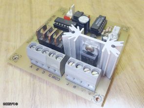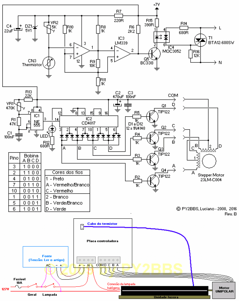
A project made for the use of Scrap Laminator as a PCB laminator. The heating resistance control in the cylinder of the laminator is provided by BTA12 triac, LM339 op amp is used in the heat control circuit, MOC3052 is used for the track driver.
A step motor is used to control the roll rotation speed of the PCB Laminator. A circuit consisting of NE555 CD4017 integrated circuits, passive components and TIP122 is used for control.
The thermistor used is the original thermistor in the heater fuser of the laminator. Each fuser originally has a thermistor used for this function. It should not be confused with the bi-metallic safety switch found in some fusers; this is only for protection purposes in order not to burn the printer in case of thermostat failure.
Measure the temperature with a multimeter and measure the resistance of the NTC when it reaches 180 degrees.
For example: If the NTC gave 10K at 180 degrees, set the trimpot to 30K.
Roughly speaking, the trimpot value should be 2 to 3 times the NTC resistance value at the target temperature.
The cut-off point of the relay is approximately the NTC value set on the trimpot. For example: If the trimpot is set to 2K, the relay will be disabled when the NTC reaches 2K.
Therefore, the NTC resistance should be measured at the target temperature. Then adjust the trimpot to approximately the same value and then fine-tune.

Important Note! The laminator heater must be of the type that uses a halogen lamp (Many models use lamps.) and aluminum tube. Those that use film and/or ceramic resistors for heating will NOT WORK! Look for a fuser that uses a halogen lamp.
Şifre-Pass: 320volt.com
source py2bbs.qsl.br/laminador.php#gsc.tab=0
Publication date: 2024/12/17