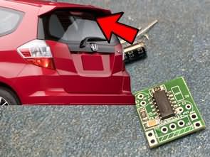
I had also heard in the news that the European Union had made it mandatory for new vehicles to have flashing brake lights, although it was said to be for “sudden braking”, but this system has been used in many cars for many years. @Bilgin.055 had shared a similar circuit in the electronic projects forum; “BRAKE – STOP FLASH CIRCUIT” I didn’t really care because I didn’t know about it, vehicles flash LEDs etc. all kinds of problems. A few days later, when I saw the same system on the upper LED brake light of the car in front of me, I really liked it 🙂
The brake flasher draws attention but it doesn’t distract or bother you. When you step on the brake, the LEDs flash 3…4 times and then stay on continuously.
According to my research, as long as the flashing is not exaggerated, there is no problem anyway, it is sold as “GS-100A Module”. Many cars have this feature as factory default.
The first circuit I applied is based on the Schmitt trigger quad nand CD4093 integrated circuit. The output uses a PNP darlington transistor to switch the brake light from the high side. But I couldn’t get the circuit to work as it was. I used a mosfet transistor and simplified the circuit a bit more.
F1 Flash Brake LED Flasher Circuit Diagram
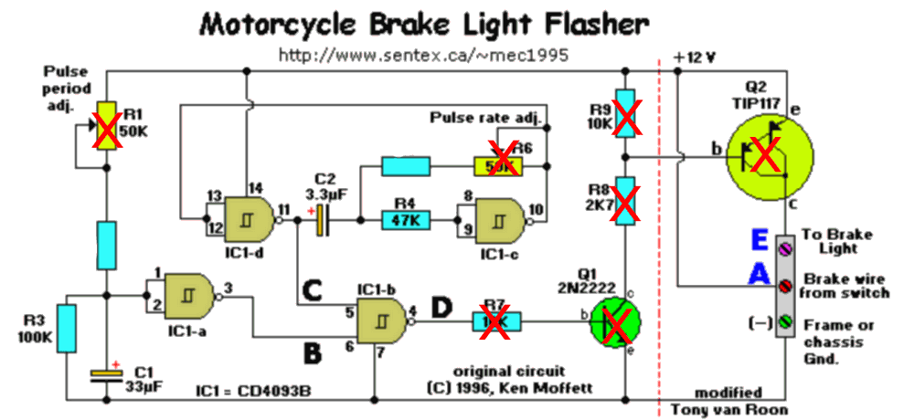
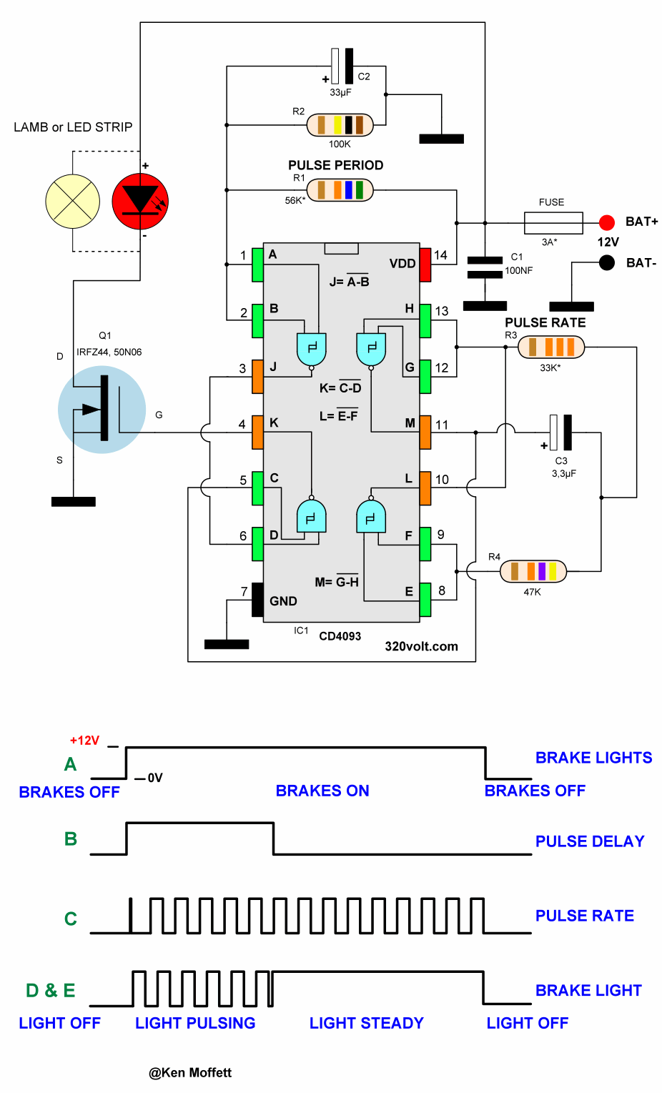
The first section provides a pulse delay to allow the brake light to flash only briefly. R1, R2, R3, C1 and IC1a form a quasi-monostable inverter. When the brake is applied, C1 is charged through R1 and R2. The output at pin 3 goes from +12 volts to zero (point B) when the voltage across R3 reaches the C1 trigger level. Trimpot R1 allows adjustment of the pulse delay time.
R3 provides a discharge to capacitor C1 after the circuit is powered down (via the brake switch wire). This means that there is no delay between brakes for the brake light to come on; the flasher will always work as it should. You can press the brake pedal as fast and as often as you can and the flasher will always work!
The second section provides the speed of the brake light. R4, R5, R6, C2, IC1c and IC1d form a free-running astable oscillator. When the brake is applied, the circuit is powered up and starts oscillating. speed is determined by the time constant of resistors R5 + R6 and capacitor C2. R6 allows the speed to be adjusted. The speed output is taken from pin 11 of IC1d (point C).
The third section combines the speed signal and the delay signal. IC1b ‘NANDS’ the two signals to produce a series of pulses followed by a constant high level (point D). This will create the On-Off sequence of the brake light.
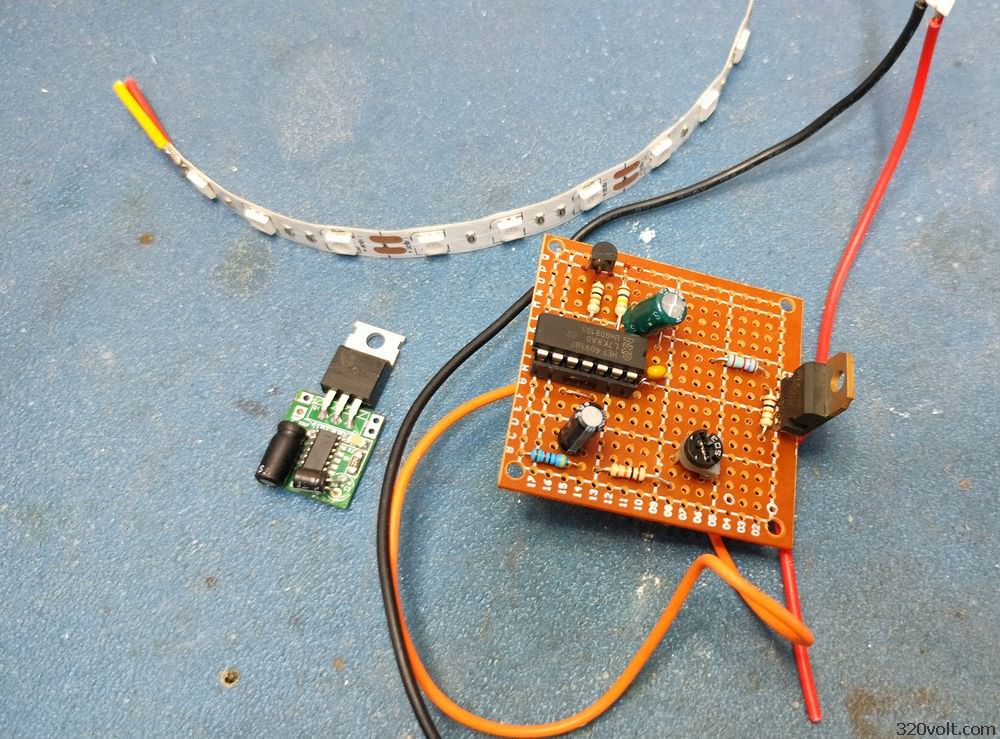
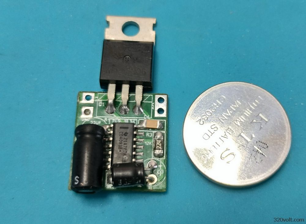
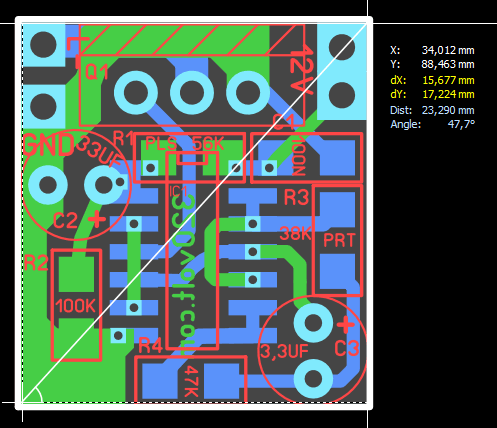
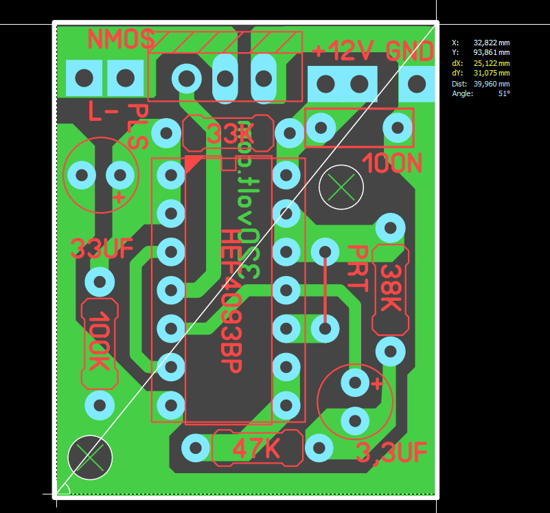
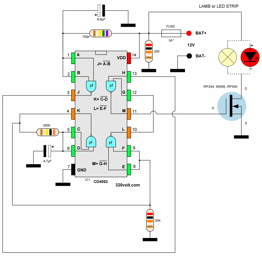
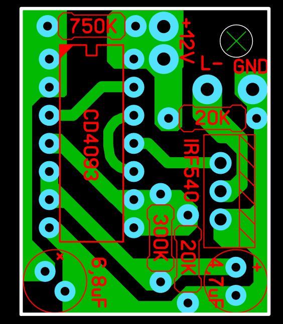
The second circuit is based on the CD4093 integrated circuit, I think its working system is better. When the brake is pressed, the LEDs light up steadily for a short time, then flash 3 times, then stay steady. Tests and details in the video
F1 Flashing Brake Light Circuit Diagram
Update: The system that will be mandatory in new vehicles is called Emergency Braking System (ESS) This support helps to detect the exact moment when the vehicle in front brakes urgently. In this way, it prevents a frontal collision or, in the worst case, reduces the range. The system warns by means of very fast flashing lights. https://www.youtube.com/watch?v=gmVKZazvxvA
Şifre-Pass: 320volt.com
source: learningelectronics.net/VA3AVR/circ/motflash.html – radiokot.ru/circuit/digital/security/02/
Publication date: 2024/12/17