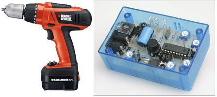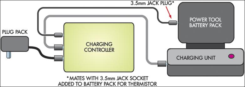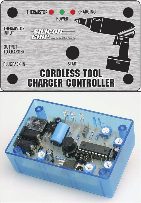
It has many features such as charging screwdrivers, which are frequently used in technical services, programming a charging circuit designed for drills, and temperature control with LED indicator. Micro Controller PIC16F88 used in charge control circuit
Charge Controller for Cordless Tools Protect your device and extend the life of your power tool’s rechargeable batteries.
Charge control circuit specifications
Charge timeout
Minimum and maximum temperature monitoring
dT/dt charged detection
Over and under temperature detection
Power, charge and thermistor indicator LEDs
Adjustable timeout limit
Adjustable dT/dt setting
Optional and adjustable high and slow charging
While these battery powered tools are useful, they are not very advanced in battery charging systems.
Most low-cost power tools include a very basic charger: a plug pack to supply power and a resistor to limit current flow to the battery. There is nothing to prevent overcharging: no timer to turn off charging when time is up, and no full charge detection.

At best, this type of basic charger shortens the life of the battery so it only needs to be replaced after relatively few charges. At worst, the base charger can destroy the battery pack the first time it is used!
If the charger is left on for too long after the battery pack is fully charged, destruction of the battery pack may occur. And it’s easy to forget to turn off the charger whenever you want. The result is severe overcharging.
You can’t even count on the fact that charging takes a certain amount of time and after that the charger can even be turned off, because the time required for a full charge depends on the state of charge of the battery pack at the start of charging.

Source: http://www.siliconchip.com.au/cms/A_108146/article.html
Battery Charge Controller schematic pcb pic assembly source code Alternative link:
Şifre-Pass: 320volt.com
Publication date: 2008/09/02 Tags: battery charger circuit, microchip projects, microcontroller projects, pic assembly example, pic16f88 projects
PIC16F88 230V Fan Controller Timer Circuit
Circuit High Voltage is working with Attention Control circuit supply from the mains without isolation were taken when making connections while testing Be Careful used microcontroller PIC16F88 high voltage to control the triac used BTA08-600TW unfortunately source pic .asm code does just hex code there at least this type of circuit design people to ready for PCBs or transformerless supply for the PIC circuit from a reliable source for those who want to
Features of PIC Timer Circuit