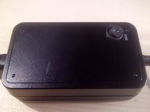
14V 3.5 A SMPS Modification for Battery Charging @Bülent NUR is one of the projects that my husband announced .. I saw a few examples of SMPS Charger Modification but I did not have the opportunity to apply it.
The system consists of two parts: first the output voltage of the SMPS adapter is set to the appropriate value for the battery charge (previously I have shared this topic: Increase Smps Voltage, and the addition of a simple current limiting circuit
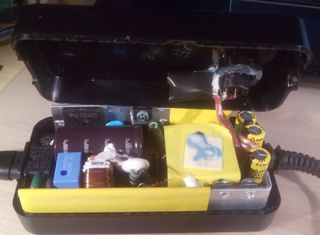
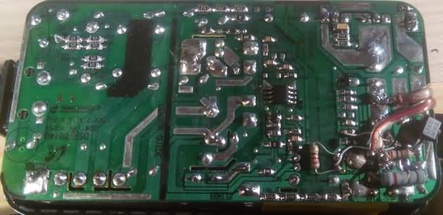
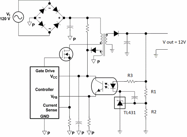
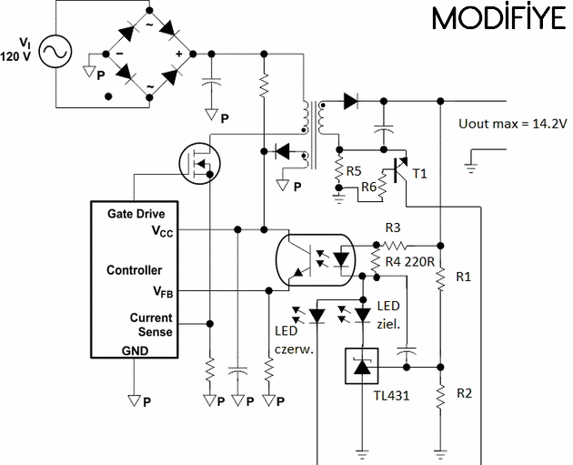
This battery charge can be tested on simple flyback SMPS adapters that I often see on the modification market. The output voltage can be 12V …. 15V The voltage will be adjusted by changing the TL431 voltage divider resistors The voltage at the TL431 REF is 2.5V * 2.5V * (1 + R1 / R2). ,
As you can see in the circuit diagram, TOP2XX TopSwitch series are structured with SMPS integrations, or UC3842, UC3843, and so on. Builds with PWM, SMPS control integrations … the advanced complicated SMPS can switch to protection of power supplies, or they can fail and be careful
Current limit value is limited to 0.65V R5 resistor. 0.75A..0.8A Resistor value for charging current 0.82 Ohm power 0.5W, resistance value for 3.5A charging current 0,22 Ohm 5W resistance T1 BC547 transistor resistance value depending on the foot of the base 1K
Original and modified SMPS Circuit Schematic
Source: elektroda.pl/rtvforum/topic3345819.html
Actually, it is easy to modify ready-made switch mode power supplies for battery charging, but whatever good measurement and testing can be done, I can finally add the schematics of the similar charge modification circuits used in the UC3842, UC3843, TOP204 integrations. Only the current, voltage control part of the secondary circuit of these circuits will be used …
The UC3842 and UC3843 are used for voltage regulation. The transformer will be used for this purpose. You will use it outside the limits of the power supply. Do not use it outside the limits of the power supply. 12V SMPS adapter can be used to charge 12V battery by setting 14.2V but using too much voltage for 6V battery will cause malfunction.
Publication date: 2018/06/09 Tags: battery charger circuit, power electronic projects, smps circuits
Ladegerät mit Flyback-Schaltnetzteil SMPS
14V 3.5 A SMPS Modifikation für Battery Charging @ Bülent NUR ist eines der Projekte, die mein Mann angekündigt hat. Ich sah ein paar Beispiele von SMPS Charger Modification, aber ich hatte keine Gelegenheit, es anzuwenden. Das System besteht aus zwei Teilen: Zuerst wird die Ausgangsspannung des SMPS-Adapters auf den passenden Wert für die Batterieladung eingestellt (vorher habe ich dieses Thema geteilt: Smps-Spannung erhöhen und eine einfache Strombegrenzungsschaltung hinzufügen)
Chargeur de batterie avec
14V 3.5 Une modification SMPS pour le chargement de la batterie @ Bülent NUR est l’un des projets que mon mari a annoncé .. J’ai vu quelques exemples de modification du chargeur SMPS mais je n’ai pas eu l’occasion de l’appliquer.
Le système se compose de deux parties: d’abord, la tension de sortie de l’adaptateur SMPS est définie sur la valeur appropriée pour la charge de la batterie (auparavant, j’ai partagé ce sujet: augmenter la tension Smps et l’ajout d’un simple circuit de limitation de courant
What is the size or model of transformer in this first image, what will be the turn of W1, W2, W3? And how to get the PCB layout of this model?