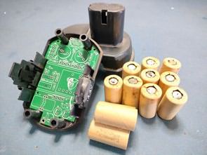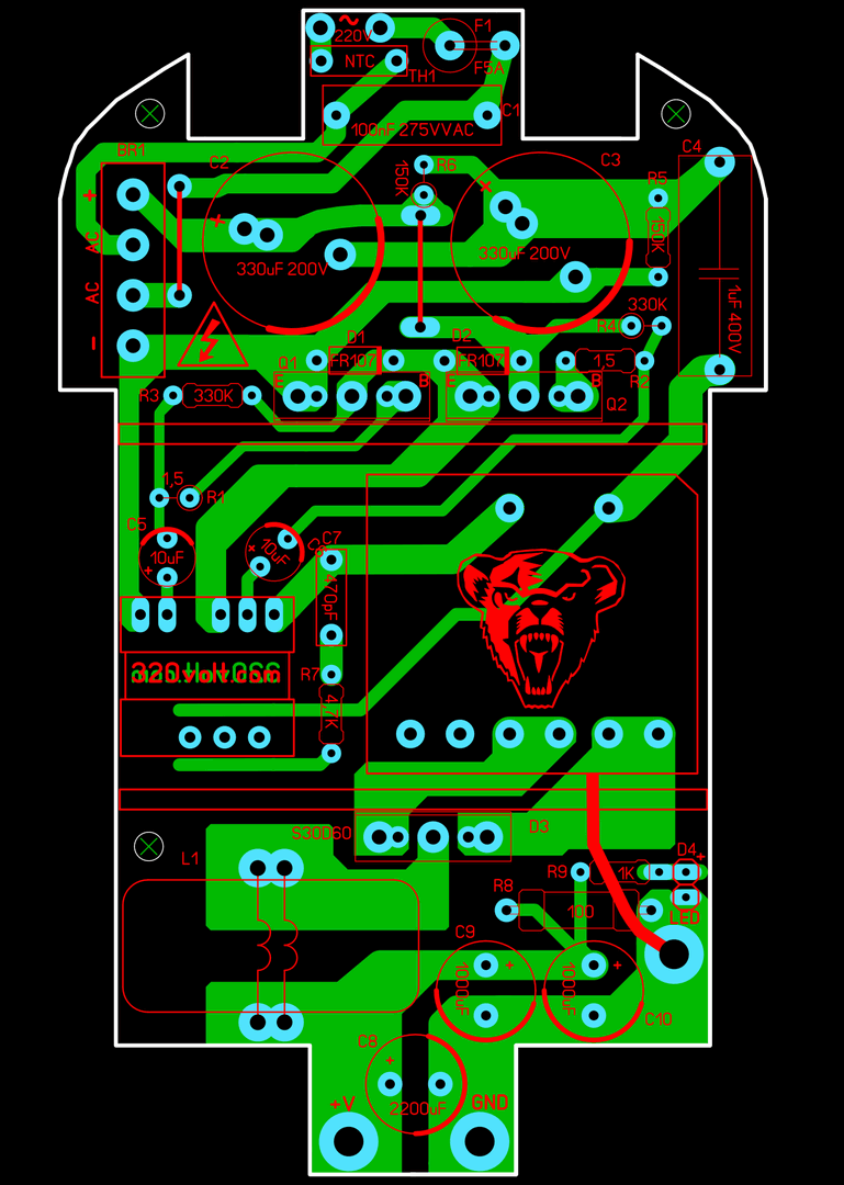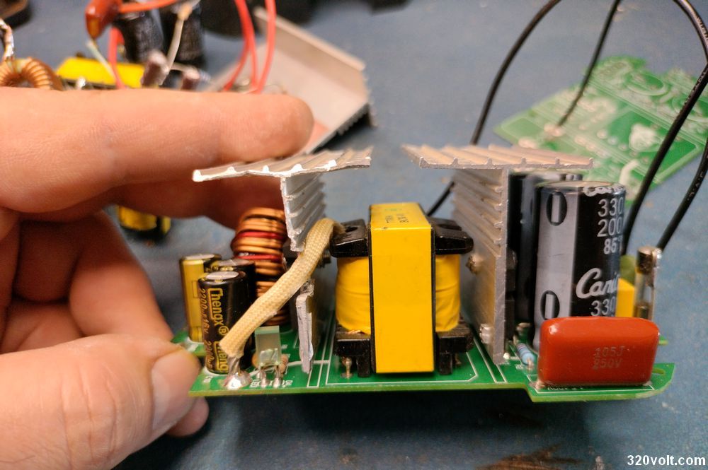
I prepared a PCB for the Simple Switch Mode Power Supply Self Osc ATX Transformer that I shared before. It is compatible with the battery boxes of many drills. Apart from the PCB design, the tests were very challenging, I encountered interesting problems and saw strange events especially in electronics repair work. The problem of this circuit is quite interesting. I finally found a solution.
The reason for the problem is that I did not use a coil at the output, but I did not use a coil in the previous circuits and I had no problems. The circuit did not work properly with this drill, I finally solved the problem by connecting a coil.
I did not use a coil in the SMPS circuit I made for the amplifier in the IR2153 SMPS Circuit 100W 800W project. When I examined many SMPS kits and the schematics of devices of large companies (IR2153, SG3525), I saw that no coil was used. I made the design by taking this as an example, it was remarkable both in terms of space and cost 🙂
But I learned this practically, it is not suitable for a single output SMPS without a symmetrical output. The weird thing is that I have made this circuit for different model drills before and none of them caused any problems. The transformers I used are the same, I checked everything but nothing… I wonder if the problem was due to the internal resistance of the motors or a material connected to the motor.
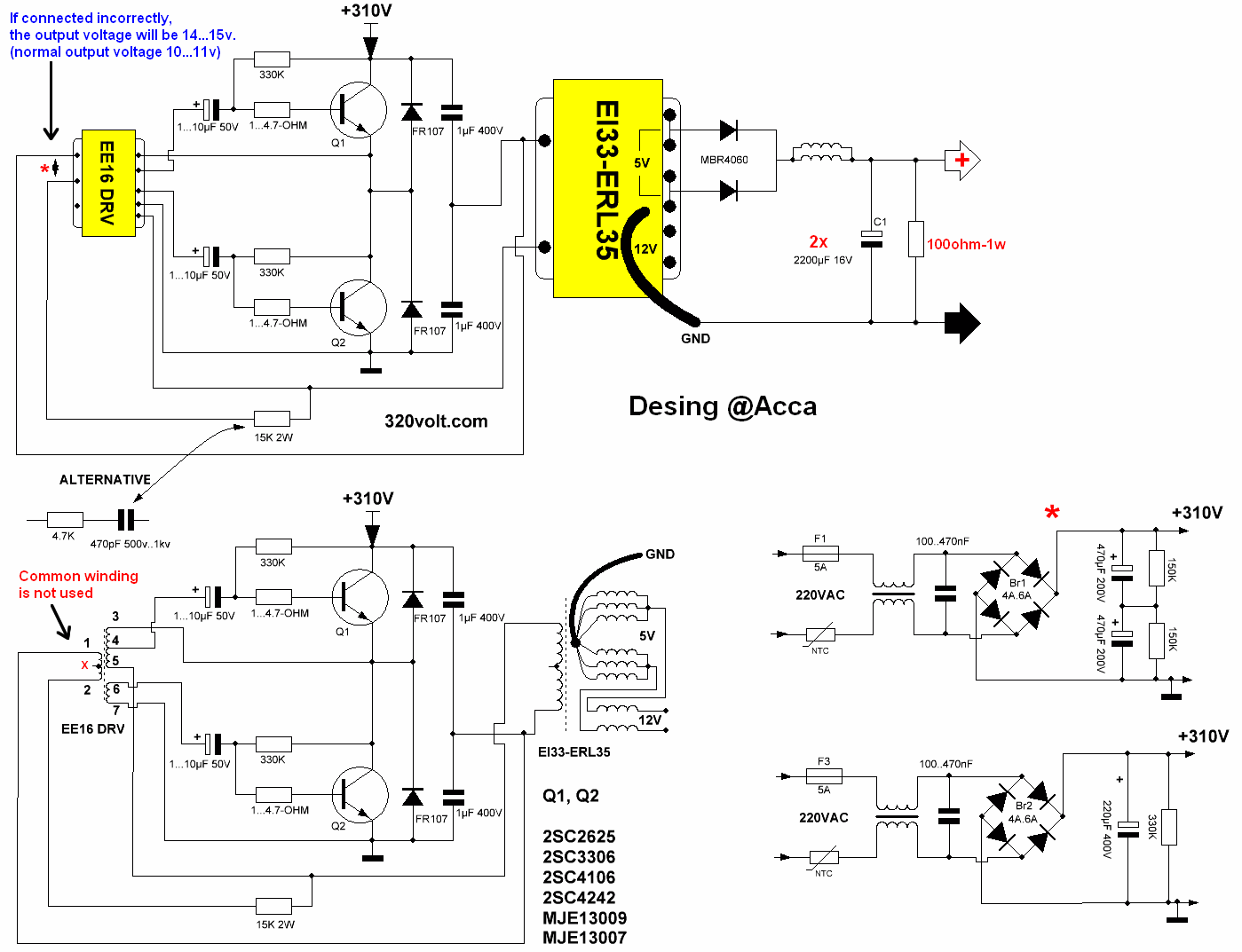
SELF OSC SMPS Circuit diagram


Şifre-Pass: 320volt.com
Publication date: 2024/12/17 Tags: power electronic projects, smps circuits, smps projects, smps schematic