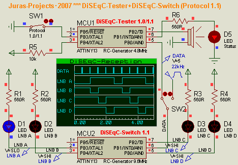
This instrument is designed to help determine the performance of 1.0 and 1.1 operating protocols and up to 4 inputs of DiSEqC switches. The device works with a 12V DC voltage source. To check the health of the disk inputs, LEDs are used, which should change every second if the disk is in good condition, and only one LED should illuminate at any given time. If one of the LEDs stays on or off, it indicates an input fault. In addition, it is possible to reduce the amplitude of 22kHz
Device parameters:
Power supply – 12V, max 200mA
Number of controlled ports – 4, using onboard LEDs
Support for DiSEqC 1.0 and DiSEqC 1.1 protocols (or 2.0 and 2.1 respectively)
2-level pilot tone – 650mV, 300mV
Command frequency – 1Hz, 2Hz, ports change in a circle
Light and sound indication of command transmission
Short circuit protection with light and sound warning (current limit)
I must say that the protocol support and switching speed depend on the firmware of the microcontroller and can be added or changed.
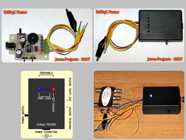
The purpose of the elements of the device:

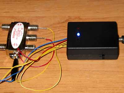
How to test a DiSEqC switch? You need to connect a device to it. We stick to the body with a crocodile on a blue wire, insert the red wire to the “Receiver” F-connector, and the remaining 4 yellow wires to the “LNB A”..”LNB D” ports of the DiSEqC switch. . We select the necessary protocol and amplitude of the pilot tone (switches on the side), turn on the power.
Every second, the red LED flashes with short pulses and a characteristic sound signal is heard. During flashing, the next (and the previous one should go out) blue LED in a circle should light up. If any port of the DiSEqC switch fails, one of the blue LEDs will be solid. As a rule, this happens at short-circuited ports.
The device itself is not afraid of a short circuit. If the “receiver” input is shorted to ground (or the red wire is connected to the alligator), the device will indicate this with a solid red LED and an audio signal with a frequency of 2.3 kHz until the short circuit. removed. Because the instrument limits its output current to approximately 150 mA, the contacts of a DiSEqC switch connected to the instrument can be shorted to ground without risk of damaging the terminals.
If one of the ports turns out to be short-circuited, when switching, the device will beep for 1 second after reaching the short-circuit port (indicating a short-circuit with a red LED). In this case, the DiSEqC switch can reset it to its original state by opening the first port that is open by default.
Therefore, if the disk is working, the device should have “lit lights” consisting of four blue LEDs. It is enough to observe for about 8 seconds at a switching speed of 1 Hz – these are two circles.
Attention! The device is powered from a stabilized DC voltage source 12V. This voltage should not be exceeded, because when it is increased, the short-circuit current will increase proportionally, ie 150 mA. Theoretically, the device can withstand a short-circuit current of up to 500 mA. You should also not reduce the supply voltage, as the device may think that there is a short circuit.
The basis of the DiSEqC tester is the ATtiny13-20PI microcontroller operating at a clock frequency of 4.8 MHz from an internal RC oscillator. The DiSEqC specification allows for carrier frequency deviations of 20%, so the instability of this generator does not affect the operation of the device. The error when calibrating this generator is 3% without calibration – 10% over the entire temperature range, which is below specification tolerances in any case.
The resistors of resistors R8 and R9 can be swapped out to achieve other message levels. Resistor R5 is required for the programmer connected to the XP1 connector to work. In the absence of this resistance, the programmer reports that the SCK line is shorted. LED HL1 does not interfere with programming. Transistor VT1 is designed for a maximum collector current of 500 mA.
Diode VD1 provides partial protection against power reversal and reduces the penetration of message pulses into the power supply circuit of the microcontroller. The zener diode VD2 is designed to limit the output current during a short circuit, allowing the microcontroller to detect the fact of a short circuit. The lower the stabilization voltage of this zener diode, the greater the short circuit current, but when this voltage increases, the short circuit detection does not work. Based on these conditions, a voltage of 7.5 V was chosen.

Source: http://juras-projects.at.tut.by/rus/projects.html DiSEqC Tester Circuit with Atmel ATtiny13 schematic hex code alternative link:
Şifre-Pass: 320volt.com
Publication date: 2008/06/16 Tags: avr project, microcontroller projects
250W 500W Hifi Amplifier Circuits
Open areas 500w and 250w HiFi amplifier for voice Friends circuit is a circuit circulating in the market that only I did some changes on the circuit. circuit so super now and is working smoothly. the output of the amplifier transistors used in German Dynacord company that uses transistors and +200 degree weather even has the ability to work. so that the circuit elements to function safely should be used in the original value.