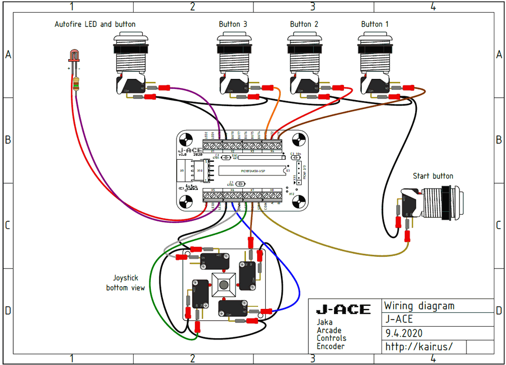
Arcade Joystick is a DIY USB keyboard encoder made with PIC18F24K50 microcontroller. It allows you to create a USB arcade stick for example or use it in a special MAME cabinet. It has easy, cheap and simple hardware to build yourself.
Features of Arcade Joystick Circuit
One additional input for autofire button. The speed of autofire is adjustable and can be configured for any action button combination.
4 outputs for LEDs. One LED is for autofire indicator, the other three LEDs serve as num lock, caps lock and scroll lock LEDs.
Full speed USB with update rate up to 1000 Hz (*Windows 1000Hz, Linux and OSX 500Hz)
Advanced anti-kickback function with zero additional delay when a button is pressed and released.
Works as standard HID keyboard or standard HID joystick.
4 separate keymaps configured as MAME players 1,2,3 and 4.
No software needed to choose between different keymaps or change autofire settings.
Autofire and keymap settings are stored in EEPROM and preserved after power down.
Full NKRO (N-key rollover) for keyboard encoder mode. All 16 inputs work simultaneously.
Shift function doubles the keycodes sent by each button. Allows to accept tokens, pause, etc. MAME specific function without dedicated button.
Works on Windows, Linux, and Mac (standard HID device, no driver needed)
Works on all major emulators (MAME, RetroPie, etc.)
Upgradeable FW (Microchip compatible HID bootloader)

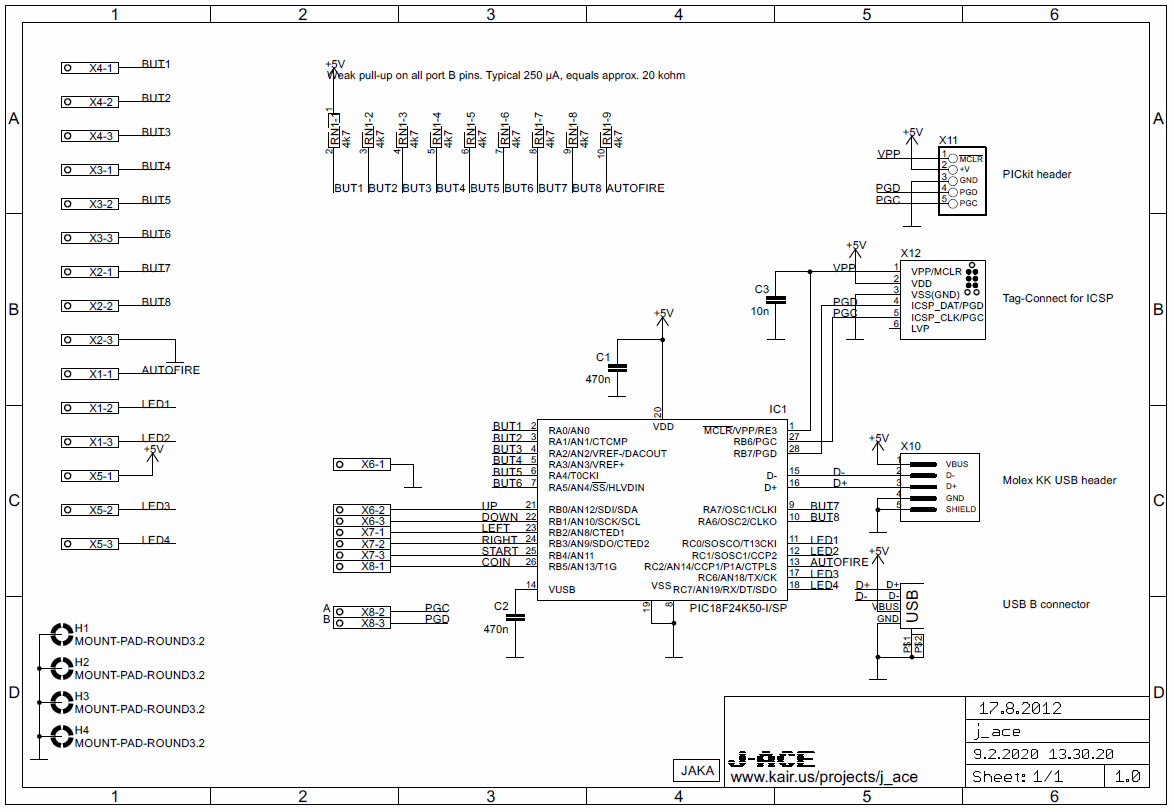
The hardware is based on the PIC18F24K50 with an integrated full-speed USB interface. The circuit has been kept as simple as possible to ensure optimum performance.
The PIC18F24K50 has integrated pull-up resistors on port B. Ports A and C require external pull-ups. External pull-ups are provided by the resistor network RN1. The pull-up resistor value is not critical, so if you can’t find a 4k7 network you can use almost anything between 1k and 47k. Capacitor C3 is not mandatory. It protects the PIC reset input from glitches that could, at least in theory, cause the USB connection to reset in noisy environments.
The board is easy to build for beginners as it uses all through-hole components. All connections to the joystick, buttons and LEDs have screw terminals for connection. There are two alternatives for the USB connection. The default is a standard USB-B connector, which will suit most needs. It is also possible to use the 5-pin header used in some cables or panel-mounted connectors, such as the Bulgin Buccaneer series panel-mounted USB connectors.
The software is written with the CCS PIC-C compiler. The polling interval is 1 ms, which means that the update rate is 1000 Hz. Button reading, debounce, scroll function, automatic firing and data transfer take a maximum of 650 µs, so the fixed update rate of 1000 Hz is real. The debounce algorithm has separate counters for each button, which means that each button responds instantly when pressed or released, independently of other inputs. Since some types of microswitches also have contact bounce during release, the debounce is applied both when the button is pressed and when it is released.


Şifre-Pass: 320volt.com
source: kair.us/projects/j_ace/index.html
Publication date: 2024/12/17 Tags: microchip projects, microcontroller projects