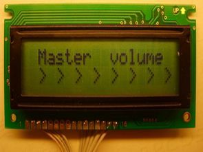
TDA7448 6 channel audio control integrated circuit with PIC Microcontroller is a very good example of the use of the application Circuit potanslar both on the lcd screen sound information, 2 × 16 volume control potentiometer and remote control can be done with both. Control for the control of the RC5 protocol used. Can be used in addition to micro controller controlled CDROM player in lieu of Pic16f876 hex files there are also source C software.
6-channel volume control on TDA7448
A simple high-quality 6-channel volume control circuit. It is assembled on a TDA7448 microcircuit manufactured by STMicroelectronics. This chip has a digital I2C interface. For control via this interface, a common, inexpensive, high-speed RISC microcontroller from Microchip PIC16F873 was used (it is possible to replace it with PIC16F873A, PIC16F876, PIC16F876A).
Developers of devices based on Microchip microcontrollers have a unique opportunity to easily connect multiple encoders without additional wiring.
Our controller is supposed to be used in 5.1 format systems. This assumes the following channels: front (left and right), surround (left and right), center and subwoofer. These channels are controlled by 4 encoders. The volume and balance mode for the front and rear are switched using the “volume / balance” button. There are also buttons for “Mute” (mute) and “StandBy” (standby mode). There is also a separate Standby line that can be used to turn off the amplifiers in the hardware. All listed control functions can be implemented via any remote control in RC5 format (from Philips home appliances).
The values of resistors and capacitors may differ by 20% from those indicated in the diagram. The display has 2 lines of 16 characters. The infrared receiver can be replaced with TSOP1736 (Vishay), SFH-506 (Siemens), TFMS5360 (Temic), ILM5360 (Integral software).
Mechanical incremental encoder, for example from the PEC12 or EC11 series. When choosing an encoder, refer to the pinout documentation. For example, PEC12 and PEC16 have different pinouts, which will require a different PCB design. In one way or another, there are several combinations of inclusions. You can determine the correct inclusion by scientific numbering.
Note: Print circuit drawing “sprint layout” prepared by “Sprint-Layout-Viewer” can open the file with the program you can get out pcb.lay
Source: http://radiokot.ru
Şifre-Pass: 320volt.com
Publication date: 2011/03/30 Tags: microchip projects, microcontroller projects, pic16f876 projects
LCD SWR Meter Circuit PIC16F877
SWR meter circuit pic16f877 microcontroller with lcd display displays the information on a printed circuit board with 2 × 16, schema diagrams in the C source code library files (adc. c, lcd8 c, swrm. c, timers), and I have 2 different hex code for 16f877a 16f877
SWR meter circuit features;
Power range 5-100W
Frequency range of 1-30 MHz
SSB operation for the Peak indicator
Forward, backward, power and SWR representation
Simple two-button interface
SWR warning and alarm LEDs