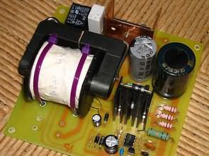
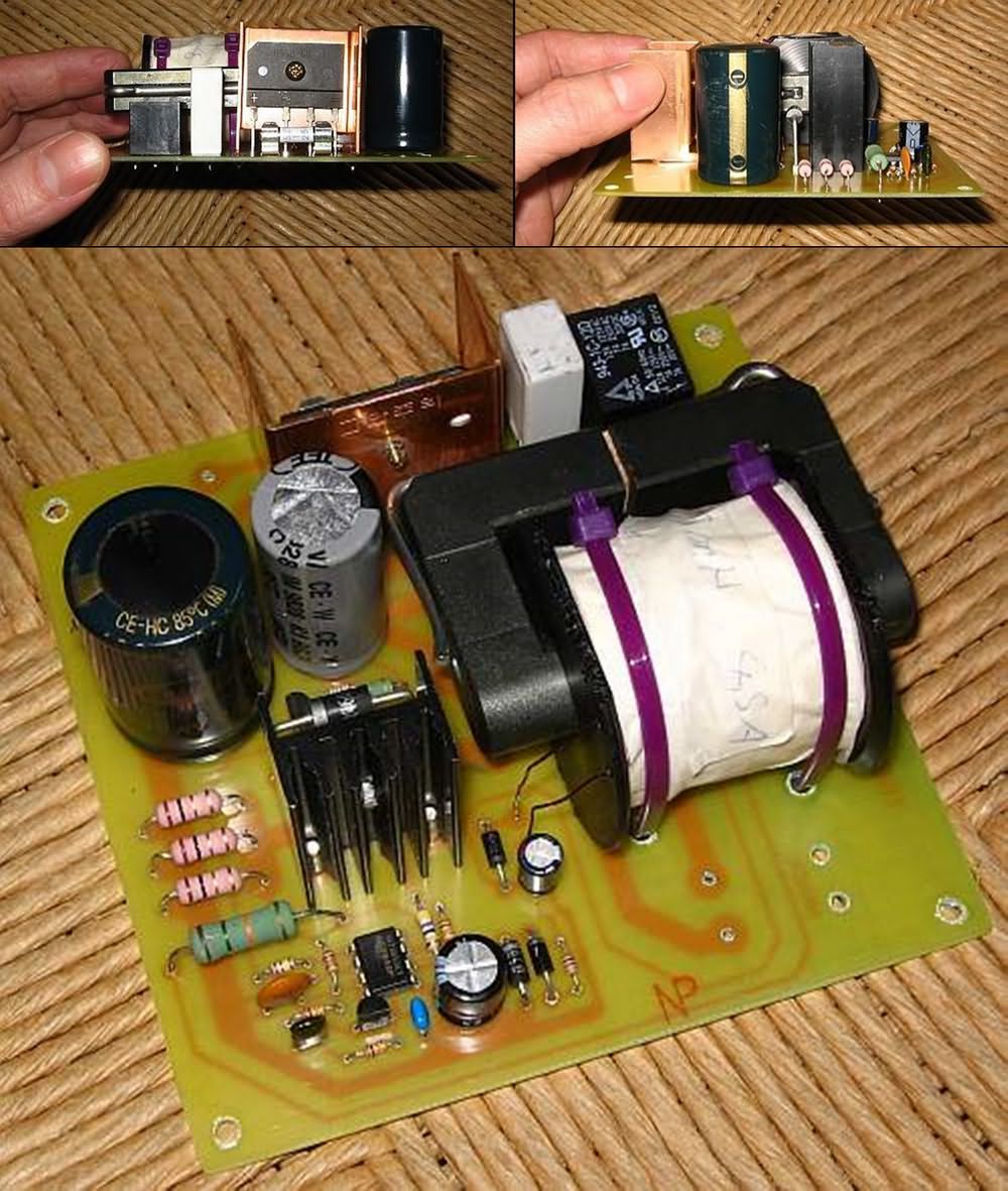
A converter circuit design was made with UC3842 as the power supply of 170VDC and 3.1 Ampere motor to operate the lathe. At first, the lathe machine was operated with a sheet metal transformer power supply, but since it took up too much space, more space was gained with a switching power supply small enough to fit on the base of the lathe.
The switching 160VDC power supply is designed to limit the current, which is important to prevent the magnets in the motor from losing their magnetism during start-up or overload conditions that will be turned on and off with the motor.
An important difference between the UC3842 Motor Power Supply and the others is that it starts quickly under full load and can be restarted immediately after being turned off. A relatively small input filter capacitor was used after the rectifier, because it was observed that the high ripple on it did not cause any problems in this circuit. In addition, the small filter capacitor discharges quickly enough after the power supply is turned off.
To limit the inrush current, there is a 2.7 ohm resistor that shorts the power supply when it reaches normal operating voltage. The supply for the UC3842 must rise quite quickly, and it also needs a large backup capacitor to be able to run it from the moment the UC3842 undervoltage lockout is released until it reaches normal voltage.
160VDC Power Supply Circuit Diagram
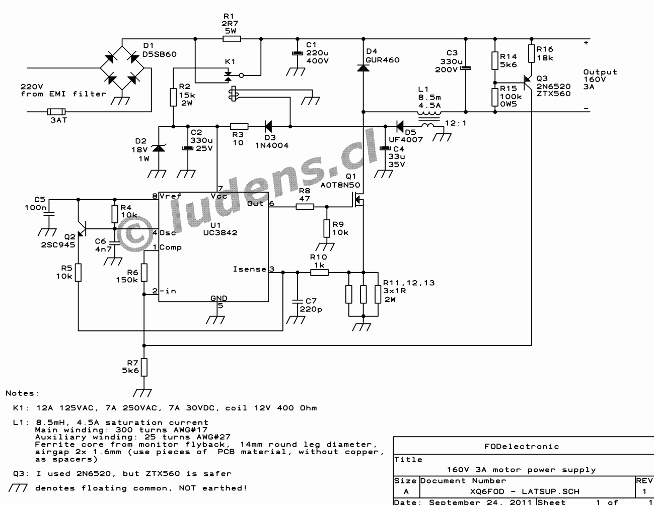
For this, 330uF is used, charged through a 15k resistor from the rectified mains to start it quickly, but to prevent overheating, this resistor is also disabled by the same relay that shorts R1 as soon as the power supply is turned on. As usual with the UC3842, during normal operation, the UC3842 is powered by an auxiliary winding on the output inductor (or transformer, if any).
The value of the output inductor is 8.5 millihenry and should not saturate at currents up to at least 4.5A. This inductor is wound on a plastic crowbar made on a lathe using the ferrite core of an old CRT monitor flyback transformer. The core needs to have an air gap. The wire needs to be of sufficient size to deliver 3 amps continuously, and the auxiliary winding that drives the UC3842 integrated circuit can be made of a thin wire with one twelfth the number of turns of the main winding.
Important: The ground symbols in the diagram refer to a floating common and should not be connected to ground! The circuit is not isolated from the mains. Remember to use an EMI filter on the 220v input
The EMI filter in the diagram I already have one on my lathe, it is designed to absorb the spark interference of the original induction motor starting circuit, so I did not add any additional filters to my power supply. However, if you plan to use a supply like this in another application, you should add an EMI filter to the input, otherwise serious interference will be emitted!
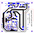
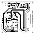
The printed circuit board is PCB x5 in size, if you reduce it to a scale of 5, your printer will print it at full scale. The PCB size is 119.4 x 114.3mm
Source: ludens.cl/Electron/latsup/latsup.html
Publication date: 2024/12/17
