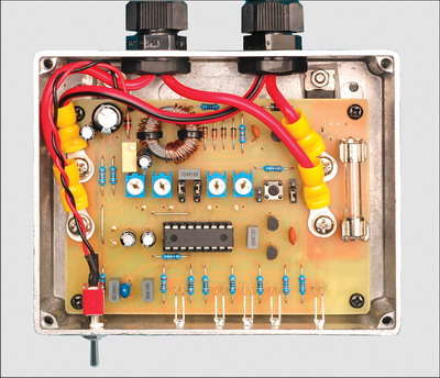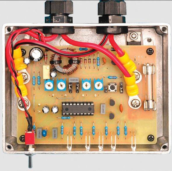
Microcontroller used in the circuit pic16f88 description circuit diagram, asm hex codes pcb file. It can provide 10 amperes of charging current. It can be used to charge 60A batteries, temperature control led indicator etc. It has features like.
Charge controller for 12V lead-acid or SLA batteries
Upgrade standard 12V lead-acid battery charger or solar cell booster to full 2 or 3 step charger using this Charge Controller. Includes temperature monitoring and LED indicator. All parameters can be adjusted for charging lead acid or Sealed Lead Acid (SLA) batteries.
Most lead-acid chargers are very simple. The main problem with this type of charger is that it will eventually overcharge the battery and seriously damage the device.
Adding a fully automatic Charger to a basic charger will correct these shortcomings. It will also extend the life of your batteries and allow a ready-to-use battery to float on charge when needed.
A typical lead acid battery charger contains a transformer. The output is rectified using two power diodes to provide raw DC to charge the battery. If the transformer is supplying too much current, a thermal cut-off opens.
It can be as simple as a battery charge indicator, zener diode, LED and resistor. The LED turns on when the voltage exceeds the breakdown voltage of the zener diode (12V) and the forward voltage of the green LED (at about 1.8V). So the LED starts to glow at 13.8V and the brightness increases as the voltage increases. Some chargers may also have an ammeter to show the charging current.
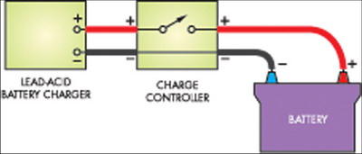
In fact, the Charge Controller is a switching device that can connect and disconnect the charger from the battery. This allows it to take control over the charge and stop charging at the correct voltage.
The Charge Controller can turn current on or off or apply it in series, ranging from 20ms to steady on every two seconds. In the first stage, called “bulk charging,” current is normally applied to continuously charge it as fast as possible. However, with low capacity batteries where the main charge current is very high, reducing the burst width reduces the average current. So, for example, if you have a 4A battery charger, the current can be reduced anywhere from 4A to 1% steps (40mA) in 1% steps, using charge rate control.
PIC16F88 Battery Charger


Source: http://www.siliconchip.com.au/cms/A_110348/article.html
12V Battery Charger circuit PCB schematic PIC16F88 pic assembly source code alternative link:
Şifre-Pass: 320volt.com
Publication date: 2008/09/02 Tags: battery charger circuit, microchip projects, microcontroller projects, pic16f88 projects
Remote Controlled Security System with PIC16F628 PIC16F88
Transmitter circut Specifications Rolling code infrared transmission Small keyfob style case Dual function buttons Randomisation of code parameters feature Synchronising of parameters feature Up to 16 identifications
Receiver circut Specifications 12V operation Up to 16 separate transmitters can be synchronised Dual function with an independent output Two alarm inputs with exit and entry delays Two door strike outputs Alarm output Arm/disarm output and LED indicator IR receive acknowledge LED Strike 1 operates on arm, disarm or both Strike 2 operates independently with momentary operation or toggle output Arm output invert option Adjustable door strike, entry/exit delay and alarm periods 200-code look ahead feature Transmitter lockout feature