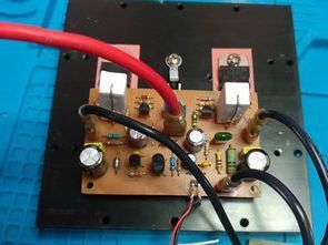
When I found a regular PCB drawing of a 100W amplifier circuit that I had in mind for a long time, I went into practice. Darlington (TIP147 TIP142) power transistors are used in the circuit output. Ideal for active speaker system or subwoofer, guitar amplifier, home theater systems, instrument amplifier… Clone version of 100W Amplifier circuit ready kit..
100W Amplifier Features:
Overload and short circuit protection*
thermal stabilization
200W music power with 4 ohm speaker
100W rms power with 4 ohm speaker
70Wrms power with 8 ohm speaker
Distortion: 0.02% @ 1KHz/10W
Damping factor: >800
Frequency response: 3Hz – 200KHz (-3dB)
Sensitivity: 0.6Vrms
Signal to noise ratio: 115dB
100W TIP147 TIP142 Amplifier Circuit Diagram
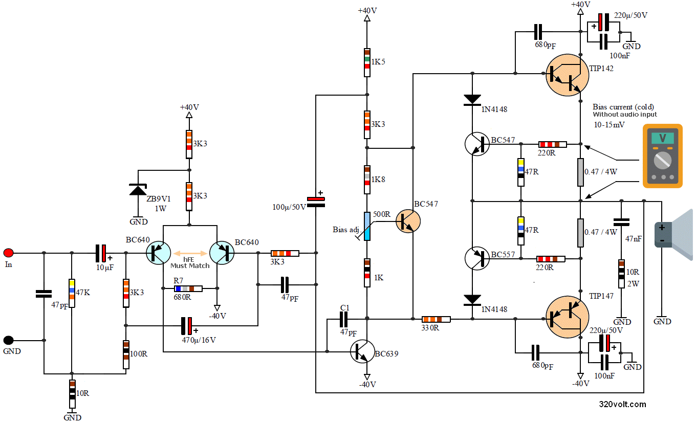
Operating voltage of 100W Amplifier circuit symmetrical max. 2X40V DC. Transformer voltage 2X25V…2X30V AC 120W…150W for mono single circuit, 250W…300W transformer for stereo two circuits is recommended. You can use 4 6A10 diodes or KBU10M bridge diodes for DC rectifier in the power supply, filter capacitors should be at least 4700uf, 6800uf would be better.
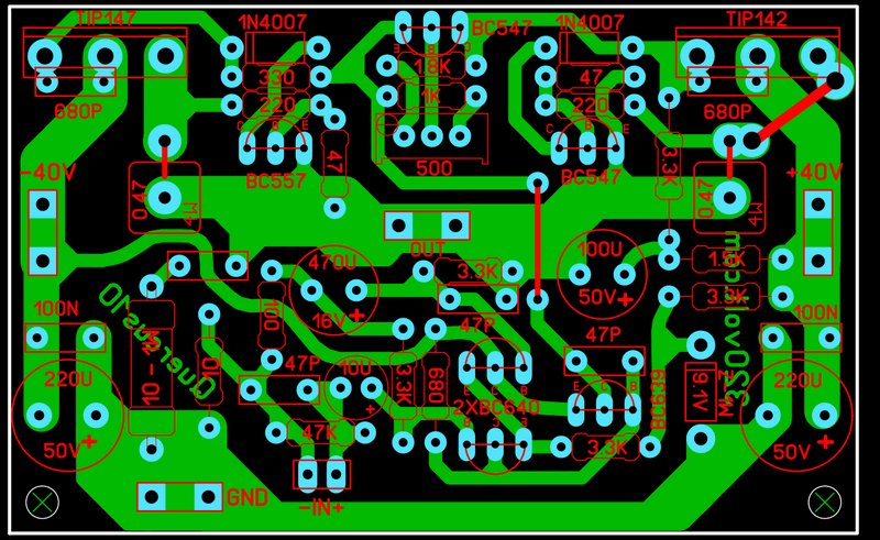
Corresponding output transistors; PNP: TIP147, BDW84, BDV66 NPN: TIP142, BDW83, BDV67 0.47 – ohm resistors connected to the emitters of the output transistors, but you can use 5w instead of 4w, but there is no market, or you can connect 2 1-ohm 2w resistors in parallel and use them. You can use a smaller thin cooler with cooler dimensions width 18cm height 8cm honeycomb length 3cm usable fan.
The hFE values of the 2 BC640 transistors at the audio input must be the same or close to each other. You can insert the heatsink with a metal as in the video of the BC547 mounted on the heatsink, or by piercing the heatsink and applying heat-conducting silicon to the hole.
Bias adjustment for thermal stabilization will be made without audio input in the case of transistors connected to the heatsink, as shown in the circuit diagram, the voltage on the 0.47 ohm resistor will be adjusted to the level of 10…15mv in general, and a 500 ohm trimpot will be adjusted. Do not turn the trimmer too fast, stop turning it when it approaches the required value and wait for the value to remain constant.
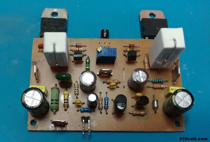
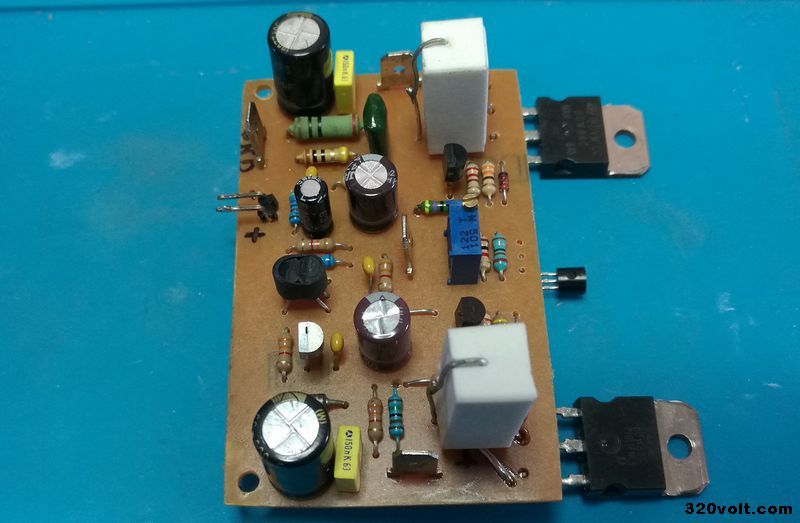
I can’t say for sure about the short circuit protection of the 100W Amp circuit because I haven’t tried it. The BDW series is pretty expensive 😀 The protection system is used in a very high quality design based on a classical method.
But material quality transistor, resistance tolerances affect operation. It would be better to observe if the protection system switches to high noise protection by changing the resistance values (200-oho-47-ohm pair) if necessary, instead of testing by direct short-circuiting (I can try in the future if possible). Also, if you can find my advice, use the original TIP147 TIP142 transistor.
There is a v2 drawing in the file, the author said that it reached 0,009 % THD (in the simulation) I did not try it, the changes made R23, R24, R20 resistors were added and the value of the 1.8k resistor was changed to 2.7k
FILE DOWNLOAD LINK LIST (in TXT format or file): 27998.rar pass: 320volt.com
source forosdeelectronica.com
Simple 100W Power Amplifier TIP147 TIP142 Transistors
There are many versions of the 100W Darlington transistor amplifier circuit. In this project, the simplest version of the circuit was made, slightly modified, and output power transistors BDW84 BDW83 were used.
Equivalents of Darlington Transistors; Darlington PNP: TIP147, BDW84, BDV66 Darlington NPN: TIP142, BDW83, BDV67 Output power is 100W, 150W RMS information is given on some sites, but probably the music power is mentioned, but I recommend you to use it with a real speaker over 100W.
It may be psychological, but the sound of darlington transistor amps is more powerful and clear to me, although I used a bass speaker (defective) in the tests, I could not understand the difference with the others, but I have such a thought according to the circuits I made in the past. 🙂
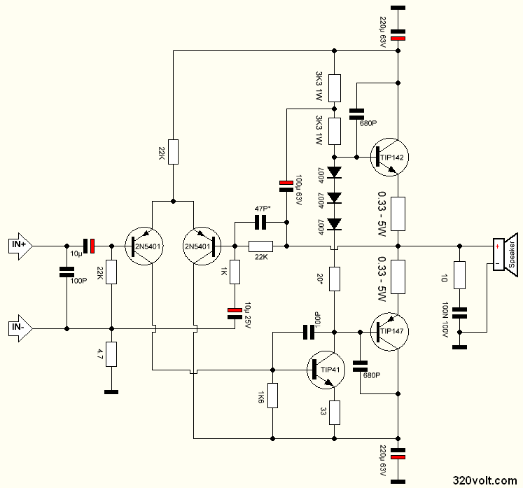
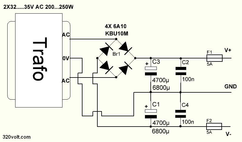
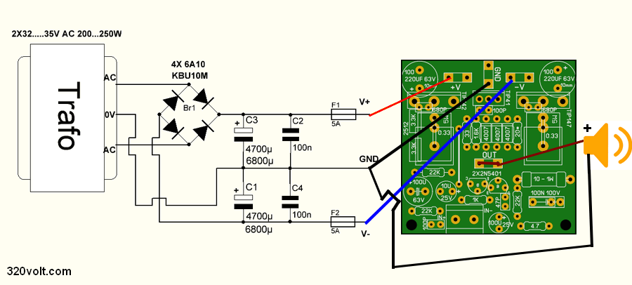
The operating voltage of the 100W Amplifier circuit is symmetrical 2X40V….48V DC. The transformer voltage can be 2X32V AC or 2X35V AC, its power is 200W…250W. You can use 4 6A10 diodes or KBU10M bridge diodes for DC rectification in the power supply circuit, filter capacitors should be at least 4700uf, 6800uf would be better. The hFE values of 2 2X2N5401 transistors in the audio input should be the same or close to each other, this detail is valid for all amplifiers with similar transistors.
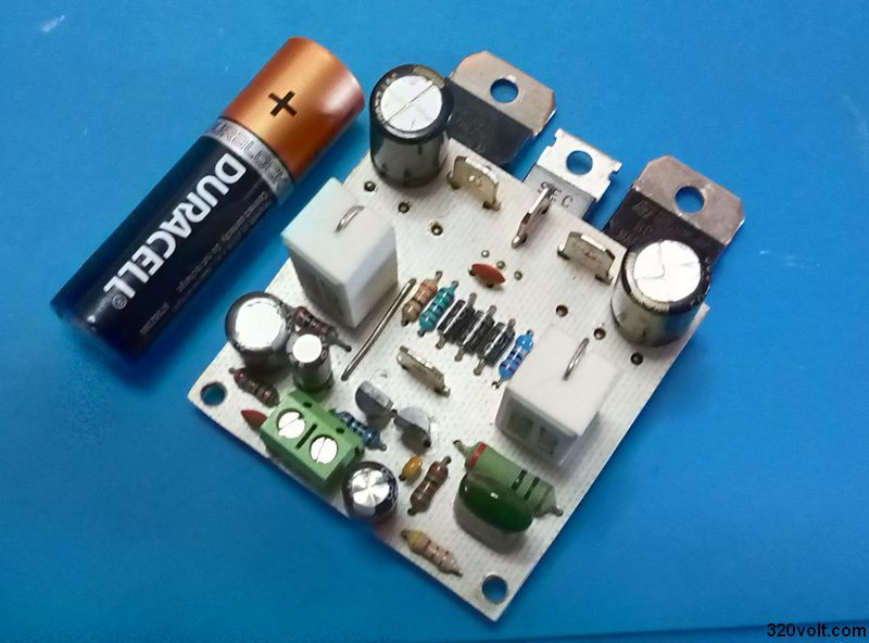
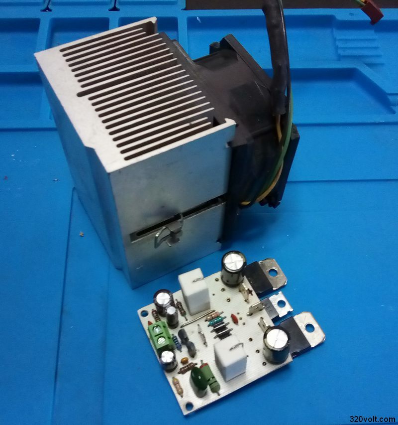
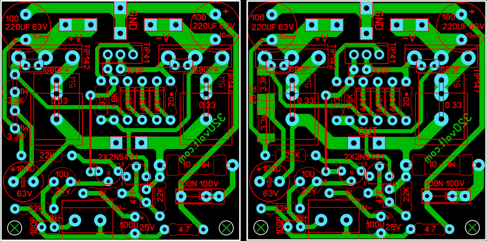
Printed circuit PCB drawing was prepared with Sprint layout 6 PCB dimensions are 48x48mm and single layer. Fits perfectly on older CPU coolers.
In the first PCB design, I used 3.3K 1W resistors SMD type, it looks more elegant 🙂 but I couldn’t find SMD resistors. I said there is no need to order 2 resistors from the web, so I mounted the resistors under the board. Afterwards, I did some editing for the DIP version of the resistors, saying never mind, and the PCB size was not changed.
Simple 100W Darlington Amplifier Circuit Diagram
Simple 100w FILE DOWNLOAD LINK LIST (in TXT format or file): 27928.rar pass: 320volt.com
Publication date: 2021/09/19 Tags: audio amplifier circuits, transistor amplifier
It is a “source” circuit. On its basis, power amplifiers have been built (and, as you can see, they are still being built) for years.
As for the topic – FINALLY, my colleague copied the amplifier with the correct quiescent current control system.
The movie – or rather the “test” (intentional quotation marks) still shows nothing. Testing a 100W power amplifier with a volume of just a few W, and “by ear”? What is that supposed to be? Showing that he is playing at all? Because nothing more.
The given parameters, taken alive from the source project, do not give 100% certainty that the copy is the same – sometimes it is enough to lead the tracks differently, slightly different elements and the original parameters will not correspond to the obtained ones.
This is a copy of the WSAH8060 kit from Velleman.
Velleman copied this from Philips / Elektor
I first saw a version of this circuit 17 years ago by a student…cheap sound for his friends.
It was wonderful then and now.
Notes Mount the driver on the heat sink…then there is no need to attach the diodes to the heat sink
Build a jig to match the output transistor (and the input ones)
Attach a fan to the heat sink
Have fun …that why we do it!!
David
The circuit is a copy of the Philips application note with BDX66 / BDX67 output transistors, I should have that somewhere in my archives. That circuit later was embraced by Elektor and published as “100 watter” in April 1982. https://www.elektormagazine.nl/magazine/elektor-198204/43140
Hello sir! Greetings from India. I have sourced most of the parts req for the simple version of the 100W amp using TIP42/47. Point 2B noted is that apparently a small decimal is missing in the input circuitry which I finally managed to ascertain as 4.7Ohms on which I feel that to avoid such simple errors we should follow the recommended standard in repeating these cases as 4¢7( here ¢ is substituted as the appropriate symbol want available on my mobile.) another ex is 4.7K, which is better of shown as 4k7. The same logic should hold good for capacitors as well as a missing decimal is ready to lose in reprints and photocopies. I hope and trust that you will note this and incorporated the same accordingly. Thank you. Another mystery here is the correct value of another resistor that was to come in series with the three diodes used between the base terminals of the opt transistors 42/47 respectively marked with an asterisk asking us to refer to text which obviously again is missing as there is no info on the above in the text. Pz enlighten me on the same as that is the only part that I need to complete the said amp… Your cooperation in this connection will be deeply appreciated. Thank you once again and sorry for the lengthy post. Have a nice day. [email protected]
Respect to the designer, I’m interested in all the resistors, what are their powers, especially these smaller resistors, it bothers me that the one in the picture looks big, so I’m not sure which one to order and what power
Hello, high power resistors are indicated in the diagram. Others resistors 1/4w