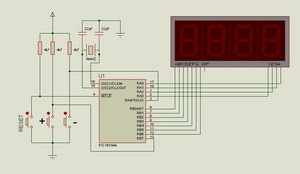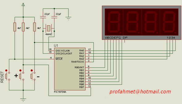
This makes the task of counter circuit. Pressing the buttons is the number of four-digit number between 0 … 9999. Press the + button on each number increases by 1. – Press button on each count is decreased by 1. The number is reset with the reset button. Do not forget to connect the PIC supply pins (of 5.p -, 14.p’s +) and common cathode 7-segment display and matrix dependent. I.e. A, B, C, D, E, F, G depends cathode pins are common as are separate 1,2,3,4.
0 9999 counter circuit diagram;

PIC16F84A 0-9999 counter circuit proteus isis simulaiton schematic pic assembly source code :
PIC16F84A 0-9999 counter circuit
Şifre-Pass: 320volt.com
Publication date: 2008/01/12 Tags: microchip projects, pic16f84 projects
VU Meter Circuits LM3914 LM3916 LM3915
LED VU Meter LM3914, LM3915, LM3916 LED driver dot bar display made with a variety of integrated circuits vu meter circuit can use with normal 3mm LEDs 5mm LEDs as well as a bar have used modules are located in the meter has been deactivated
Sprint Layout PCB file the prepared project with a well-designed double-sided PCBs used 4 integrated LED bar display while the
Eagle PCB and schematics files prepared with a drawing program finished version of the project
PIC16F84A 0-9999 Zählerschaltung
PIC16F84A 0-9999 Zählerschaltung
Dies macht die Aufgabe der Zählerschaltung. Durch Drücken der Tasten wird die vierstellige Zahl zwischen 0 und 9999 angezeigt. Durch Drücken der Taste + wird jede Zahl um 1 erhöht. – Durch Drücken der Taste wird jede Zählung um 1 verringert. Die Zahl wird mit der Reset-Taste zurückgesetzt. Vergessen Sie nicht, die PIC-Versorgungspins (von 5.p -, 14.p’s +) und die gemeinsame 7-Segment-Kathodenanzeige und matrixabhängig anzuschließen. Das heißt A, B, C, D, E, F, G hängen davon ab, dass Kathodenstifte gemeinsam sind, ebenso wie separate 1,2,3,4.
0 9999 Zählerschaltplan
Schaltung
proteus simulation and asm hex code: https://320volt.com/wp-content/list/83.zip pass: 320volt.com