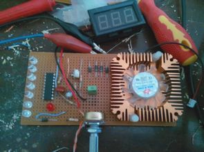
Circuit 12v battery charger circuit was made for cases according to regulated power supply olarakda available voltage indicator and the battery is full voltage for cutting LM3914 integrated were used .. the battery is full voltage to cut the relay additional circuit LM3914 integrates 10 of the leg connecting to.
Battery charging circuit diagram
first 5k pot LM317 output. set with ( 14.4v 13.8V … ) in the 10k pot LM3914. 13.8V or 14.4V with the latest LED will illuminate when the adjusted number 10 in LED lights are triggered BC547 transistor pulls the relay contacts .. LM317 1 amp gives you the power to 3 amps to 5 amps LM350 LM338 can use ..
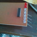
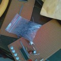
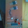
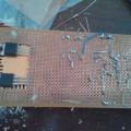
Images of the battery charging circuit
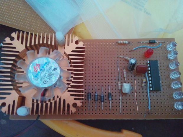

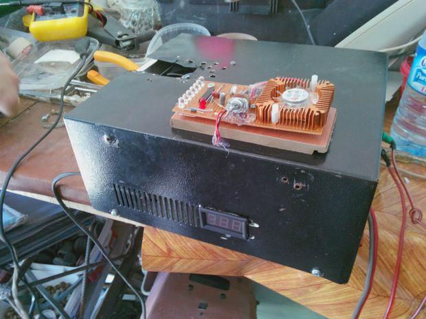
Publication date: 2013/11/06 Tags: battery charger circuit, power electronic projects
SIM900 Module PCB AVR Applications
Simcom Sim900 GSM module produced by the company prepared for the PCB module and ATMEGA32 microcontroller based on Nokia 3310 lcd display GSM module for remote control application SIM900D (place of origin: CN; proteus isis circuit), free with operating systems, Linux-style with the program PuTTY SSH protocol used by a connection through the application. PCB files prepared with Diptrace source. “dip” drawing files with the extension.
Akkuladeschaltung mit LM317
Schaltung 12v-Akku-Ladegerät-Schaltung wurde für die Fälle nach geregelten Netzteil olarakda zur Verfügung-voltage-Anzeige und die Batterie ist voll, Spannung zum schneiden LM3914 integriert wurden verwendet, .. die Batterie ist voll, Spannung geschnitten, um die zusätzliche relais-Schaltung LM3914 integriert 10 des Beins verbinden.