DSPIC30F3013 Dijital VCO projesinin kaynak kodları verilmiş ayrıca wave table generator ve tuning table generator programlarının C++’da yazılan kaynak kodlarıda paylaşımış. Ayrıca hesaplama ve formüller hakkında bilgilerde bulunuyor.
Yazarın açıklaması; DSPIC30F3013 ile oluşturulmuş dijital VCO devresi. Bir arama tablosu kullanılarak dspic’te üstel dönüşüm gerçekleştirilen sayısal olarak kontrol edilen bir osilatördür (NCO). NCO fazı bir üçgen dalga formu aramak için kullanılır. Üçgen dalga 8 bitlik bir R2R DAC ile verilir. Normal VCO dalga formları, sinüs, testere dişi ve PWM, analog devre kullanılarak üretilir. Bu ilk sürüm için geleneksel bir VCO oluşturmak istedim, ancak gelecekteki sürümler ek dalga formları içerebilir. Girişler 1V / Octave, üstel FM, senkron ve PWM’dir. Üç frekans kontrolü var. Bir kaba ve ince üstel kontrol 1V / Oct ve üstel FM girişleriyle toplanır. Dspic’in ADC’de yerleşik olarak kullanılmasıyla doğrusal bir ince kontrol de sağlanmıştır.
Dspic’in akümülatörlerinin her ikisi de kullanılıyor. Akümülatör A, NCO için 32 bitlik bir faz akümülatörü görevi görür. Akümülatör B, 24 bitlik bir ayar sözcüğü depolar. NCO 500khz’de çalışmaktadır. Yüksek örnekleme oranı, takma oranını azaltmak için kullanılır.

Kontrol voltajı bir 16bit ADC’ye gelir ve yaklaşık 100 khz’de örneklenir. ADC okuması daha sonra birinci dereceden bir dijital filtreden geçirilir. Bu filtre çok ucuz ve dsp talimatları olmadan uygulanır. Filtrelenmiş ADC okuma değerinin düşük 12 biti, bir 24 bit ayarlama değeri sağlayan bir arama tablosu indekslemektedir. ADC okumasının üst 4 biti, bir oktav çarpanı değeri aramak için kullanılır. Çarpma, MAC dsp komutları kullanılarak iki adımda yapılır.
VCO’nun performansı umduğum kadar iyi. Sayacım ölçebildiği gibi birkaç oktav üzerinden izlendi ve kenton midi-CV dönüştürücümden daha iyi izliyordu. ADC girişindeki gürültüden kaynaklanan bazı frekans titreşimleri var. Bundan kaçınmayı umduğum dijital filtreyi eklememin nedeni de bu.
Bir VCDO ile ilgili en sevdiğim şeylerden biri ayarlama kolaylığı. Sık sık ayarlamanız gerekmiyor. Gerektiğinde, referans frekansı veya frekans ölçer olmadan çok yakın ayarlama yapılabilir. ADC referansına bir kalibrasyon butonu ve trim potu dahil ettim. Düğme tutulduğunda ve ADC okumasının 12 biti 0 olduğunda, bir LED yanar. Bu, VCO’nun tam bir oktav değerine ayarlandığını gözle görülür şekilde gösterme etkisine sahiptir.
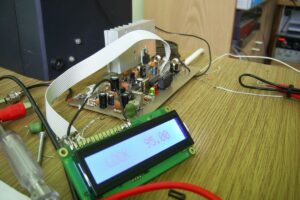
VCO Devresi Test Sesleri;
Update: After playing with this VCO for a while and thinking about the design. I think the idea is good, but the implementation could use some work. This design provides some tuning assistance but a complete autotune feature would be much nicer. The main problem I have is the high power consumption. I have been working with the NXP LPC1700 and LPC2000 controllers a lot and think that those would be a much better choice. In the future, i also plan to build my digital modules to use a third +5V power supply rather than regulating a 15V down to 5V. If anyone is considering building this as is, know that I am currently not using this in my synth.
This is a digital VCO built with a dspic30f3013. It is a numerically controlled oscillator (NCO) with the exponential conversion performed in the dspic using a lookup table. The NCO phase is used to lookup a triangle waveform. The triangle wave is output through an 8bit R2R DAC. The normal VCO waveforms, sine, sawtooth, and PWM, are generated using analog circuitry. For this first version, I wanted to create a traditional VCO, but future versions may include additional waveforms. The inputs are 1V/Octave, exponential FM, sync, and PWM. There are three frequency controls. A coarse, and fine exponential control are summed with the 1V/Oct and exponential FM inputs. A linear fine control is also provided using the dspic’s built in ADC.
Both of the dspic’s accumulators are used. Accumulator A acts as a 32bit phase accumulator for the NCO. Accumulator B stores a 24bit tuning word. The NCO operates at 500khz. The high sample rate is used to reduce aliasing. There is still a small amount of aliasing audible, I can hear it with my headphones but not so much on my speakers.
The control voltage comes into a 16bit ADC and is sampled at about 100khz. The ADC reading is then passed through a first order digital filter. This filter is very inexpensive and is implemented without the dsp instructions. The lower 12 bits of the filtered ADC reading index a lookup table which provides a 24bit tuning value. The upper 4 bits of the ADC reading are used to lookup an octave multiplier value. The multiplication is done in two steps using MAC dsp instructions.
The analog waveshapers are similar to most triangle core VCOs. I have done something a bit different with the sine shaper. This circuit works wonderfully. It uses an OTA with negative feedback. A description of this circuit can be seen in the paper I wrote a few years back (here). The resistor values for the sine shaper came from one that Ian Fritz built. The saw shaper was also adapted from Ian Fritz’ triangle VCO.
The performance of the VCO is as good as I’d hoped. It tracked over several octaves as well as my meter could measure and it was tracking better than my kenton midi-CV converter. There is some frequency jitter caused by noise at the ADC input. That is the reason I added the digital filter which I had originally had hoped to avoid.
One my favorite things about having a VCDO is the ease of tuning. I don’t expect to need to tune it often. When needed, very close tuning can be achieved without a reference frequency or frequency meter. I included a calibrate button and trim pot on the ADC reference. When the button is held and the lower 12 bits of the ADC reading are 0, a LED is lit. This has the effect of visibly showing when the VCO is set to an exact multiple of octaves.
The design is stable, but I still have one concern. That is the power consumption of the dspic while running at 120MHz. The dspic gets quite warm but not so hot that It burns my finger. The regulator however does get quite hot. I am certain it is within spec with a current headroom of 20-50mA depending on the ambient temperature. But It would have been a good idea to drop the input voltage through some diodes. The whole circuit draws 120mA from the +15V supply, so there is a price to pay for the stability that comes with being digital. A better solution would be to use a processor with a more efficient architecture. The dspic requires 4 clock cycles for the fastest instructions and I don’t think I’m using the dsp instructions enough to use a dspic.
I will probably build one more of this version, then use it as a base for a future design. The future design will have more features that are difficult to achieve with analog VCOs. The main goals for version 2 will be reduced power consumption and ADC cost.
My oscillator is an NCO. This is the same thing that DDS ICs use. you can find lots of information about them from analog devices’ web site. it basically adds a constant *tuning* value to an accumulator at some sample rate. the value of the tuning word determines the frequency. if you look at the accumulator value over time, it will increase until it overflows then repeats. the accumulator value is the oscillator phase. it is a ramp wave form but can be used to lookup any other wave form from a lookup table. the tuning word can be any number up to 1/2 the maximum phase accumulator value. In practice, it should stay much less than this to avoid aliasing. A 32bit phase accumulator will give good frequency resolution.
Kaynak: homebuilthardware.com/index.php/projects/dspicvcdo/