Uçak Servo Kontrolör projesi, çoğu iyi tasarım gibi bir ihtiyaç ürünüdür. Birkaç yıldır model uçaklar yapıyor ve uçuruyorum ve kontrol yüzeyi atışlarını ayarlamak benim için her zaman bir engel olmuştur. Uçak hakkında bilgisi olmayanlar için, bir yönde veya diğer yönde hareket eden ve havanın uçak tarafından akış şeklini değiştiren “kontrol yüzeyleri” tarafından kontrol edilirler. Bu, uçağın belirli bir şekilde yön değiştirmesine neden olur.
Uçağın tasarımına bağlı olarak kontrol yüzeyinin hareket etmesi gereken miktar farklı olabilir. Bu nedenle, yeni bir uçak kurarken, tasarım spesifikasyonları dahilinde olduklarından emin olmak için kontrol yüzeylerinin fırlatmasını ölçmek ve ayarlamak önemlidir. Bunun zor olabilmesinin nedeni, radyo vericisi üzerindeki kontrol çubuklarının yay yüklü olması ve bu nedenle bir elin uçağı ölçmeye çalışırken diğer elin onları tutmasını gerektirmesidir. Ölçümleri yapmak için iki elimi de kullanabilirsem çok daha kolay olacağına karar verdim. Üç gereksinimi karşılayabilecek bir uçak servo kontrol cihazının oluşturulması gerekiyordu:

Kapsamlı GPIO, dahili bir osilatör ve kolay bir programlama arabirimi ile Atmel ATmege16, üzerine inşa edilecek iyi bir mikro denetleyiciydi. Çıktıları, doğrudan uçak servolarının kontrol sinyallerini çalıştırabilirken, yine de butonları okumak ve bir LCD ekranla arayüz oluşturmak için bol miktarda G/Ç bırakabilir. 8 MHz’de çalışırken, yanıt veren bir kullanıcı arabirimini korurken, dalga biçimi ISR’lerine hizmet vermek için bol miktarda beygir gücü vardı.
Tüm projelerde olduğu gibi, tüm projedeki ayrıntılar dikkatimi dağıtmasın diye sistemi parça parça kurdum. R/C servoları için spesifikasyon, kontrol darbelerinin 1-2 ms uzunluğunda olacağını (1ms tam saat yönünün tersine ve 2ms tam saat yönünde) ve yaklaşık 20 ms aralıklı olacağını belirtir. Bu nedenle ilk işim, yedi kanalın hepsinde aynı anda gerekli dalga formlarını yapmaktı. Yazar: Ryan Knowlton

My Airplane Servo Controller project is a product of necessity as most good designs are. I’ve been building and flying model aircraft for a number of years, and setting up control surface throws has always been a stumbling block for me. For those who don’t know about aircraft, they are controlled by “control surfaces” that move in one direction or the other and change the way that the air flows by the plane. This causes the plane to change direction in a certain way.
Depending on the design of the aircraft, the amount that the control surface should move may be different. Therefore, when setting up a new aircraft, it is important to measure and adjust the throw of the control surfaces to make sure they are within the design specifications. The reason that this can be difficult is because the control sticks on the radio transmitter are spring-loaded and therefore require one hand to be holding them while the other tries to measure the aircraft. I decided that it would be much easier if I could have both hands available to do the measurements. An airplane servo controller needed to be build that could meet three requirements:
1. The aircraft transmitter should not be needed
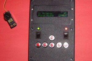
2. Servos should be able to be set to any position and held there
3. The positions of the servos should be shown to aid in setting up computer radios (i.e. Dual-Rate functions)With ample GPIO, an internal oscillator, and an easy programming interface, the Atmel ATmege16 was a good microcontroller to build around. Its outputs could directly drive the control signals of the aircraft servos while still leaving plenty of I/O for reading push buttons and interfacing with an LCD display. Running at 8 MHz, there was plenty of horsepower to service waveform ISRs while still maintaining a responsive user interface.
Once I had chosen a target microcontroller, I next needed a compiler. After looking around, I found that there were two options: AVR Studio and avr-gcc. Always being one to favor open source projects, I downloaded WinAVR which includes a source editor (Programmers Notepad) and the avr-gcc compiler.
As with all projects, I built the system one piece at a time so that I wouldn’t get distracted by the details of the entire project. The specification for R/C servos states that the control pulses will be 1-2 ms long (1ms being full counter-clockwise and 2ms being full clockwise) and will be spaced approximately 20 ms apart. Therefore, my first task was to make the required waveforms on all seven channels simultaneously. Author: Ryan Knowlton


