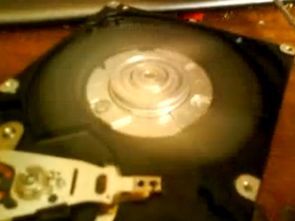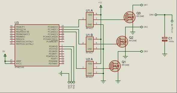
Fırçasız Motor sürücü devresinde Atmega8 ile bilgisayarlarda kullanılan hard diskin motoru kontrol edilmiş atmega 8 çıkışları mosfetler (IR4427, IRFZ44) ile güçlendirilip motorun A,B,C,D uçlarına bağlanmış . Yazılım C dili ile yazılmış kullanılan derleyici CV AVR Uygulama devresinde frekans için kristal yerine iç osilatör kullanılmış ama uzun süreli çalışma için kristal osilatör öneriliyor testlerde motorun 30.000 devir yaptığı tahmin ediliyor.

Kaynak: http://avrlab.com/
atmega8-hard-disk-hdd-fircasiz-motor-surucu
Şifre-Pass: 320volt.com
Yayım tarihi: 2011/08/04 Etiketler: ATmega8 devreleri, atmega8 uygulamaları, atmel avr projeleri, fırçasız motor sürücü, hdd motor, motor kontrol

paylaşım için teşekkürler gerçekten güzel bir çalışma uzun zaman önce buna benzer bir devre aradım fakat bir türlü istediğim gibi birşey bulamamıştım bir sorum olacak bu devrede atmega8 yerine pic serisi bir entegre kullananılabirmi ve olursa hangisini önerirsiniz…
If you interrested about BLDC controller please send Email: [email protected] because I am autor of this device 😉
Teşekkürler
Não tem código fonte?
Kaynak kodlar 220.htm dosyasında yazıyor
#include
#ifndef RXB8
#define RXB8 1
#endif
#ifndef TXB8
#define TXB8 0
#endif
#ifndef UPE
#define UPE 2
#endif
#ifndef DOR
#define DOR 3
#endif
#ifndef FE
#define FE 4
#endif
#ifndef UDRE
#define UDRE 5
#endif
#ifndef RXC
#define RXC 7
#endif
#define FRAMING_ERROR (1<
char state;
// Timer1 output compare A interrupt service routine
interrupt [TIM1_COMPA] void timer1_compa_isr(void)
{
// Place your code here
switch (state){
case 0:
PORTC=1;
break;
case 1:
PORTC=3;
break;
case 2:
PORTC=2;
break;
case 3:
PORTC=6;
break;
case 4:
PORTC=4;
break;
case 5:
PORTC=5;
break;
}
if (state<5)
state++;
else state=0;
}
// Declare your global variables here
void main(void)
{
// Declare your local variables here
// Input/Output Ports initialization
// Port A initialization
// Func7=In Func6=In Func5=In Func4=In Func3=In Func2=In Func1=In Func0=In
// State7=T State6=T State5=T State4=T State3=T State2=T State1=T State0=T
//PORTA=0x00;
//DDRA=0x00;
// Port B initialization
// Func7=In Func6=In Func5=In Func4=In Func3=In Func2=In Func1=In Func0=In
// State7=T State6=T State5=T State4=T State3=T State2=T State1=T State0=T
PORTB=0x00;
DDRB=0x00;
// Port C initialization
// Func7=In Func6=In Func5=In Func4=In Func3=In Func2=Out Func1=Out Func0=Out
// State7=T State6=T State5=T State4=T State3=T State2=0 State1=0 State0=0
PORTC=0x00;
DDRC=0x07;
// Port D initialization
// Func7=In Func6=In Func5=In Func4=In Func3=In Func2=In Func1=In Func0=In
// State7=T State6=T State5=T State4=T State3=T State2=T State1=T State0=T
PORTD=0x00;
DDRD=0x00;
// Timer/Counter 0 initialization
// Clock source: System Clock
// Clock value: Timer 0 Stopped
// Mode: Normal top=FFh
// OC0 output: Disconnected
TCCR0=0x00;
TCNT0=0x00;
//OCR0=0x00;
// Timer/Counter 1 initialization
// Clock source: System Clock
// Clock value: 8000,000 kHz
// Mode: CTC top=OCR1A
// OC1A output: Discon.
// OC1B output: Discon.
// Noise Canceler: Off
// Input Capture on Falling Edge
// Timer1 Overflow Interrupt: Off
// Input Capture Interrupt: Off
// Compare A Match Interrupt: On
// Compare B Match Interrupt: Off
TCCR1A=0x00;
TCCR1B=0x09;
TCNT1H=0x00;
TCNT1L=0x00;
ICR1H=0x00;
ICR1L=0x00;
OCR1AH=0xFF;
OCR1AL=0xFF;
OCR1BH=0x00;
OCR1BL=0x00;
// Timer/Counter 2 initialization
// Clock source: System Clock
// Clock value: Timer2 Stopped
// Mode: Normal top=FFh
// OC2 output: Disconnected
ASSR=0x00;
TCCR2=0x00;
TCNT2=0x00;
OCR2=0x00;
// External Interrupt(s) initialization
// INT0: Off
// INT1: Off
// INT2: Off
MCUCR=0x00;
MCUCSR=0x00;
// Timer(s)/Counter(s) Interrupt(s) initialization
TIMSK=0x10;
// USART initialization
// Communication Parameters: 8 Data, 1 Stop, No Parity
// USART Receiver: On
// USART Transmitter: On
// USART Mode: Asynchronous
// USART Baud Rate: 38400
UCSRA=0x00;
UCSRB=0xD8;
UCSRC=0x86;
UBRRH=0x00;
UBRRL=0x0C;
// Analog Comparator initialization
// Analog Comparator: Off
// Analog Comparator Input Capture by Timer/Counter 1: Off
ACSR=0x80;
SFIOR=0x00;
// Global enable interrupts
#asm("sei")
while (1)
{
// Place your code here
OCR1A=lvl;
};
}